
Contributing editor
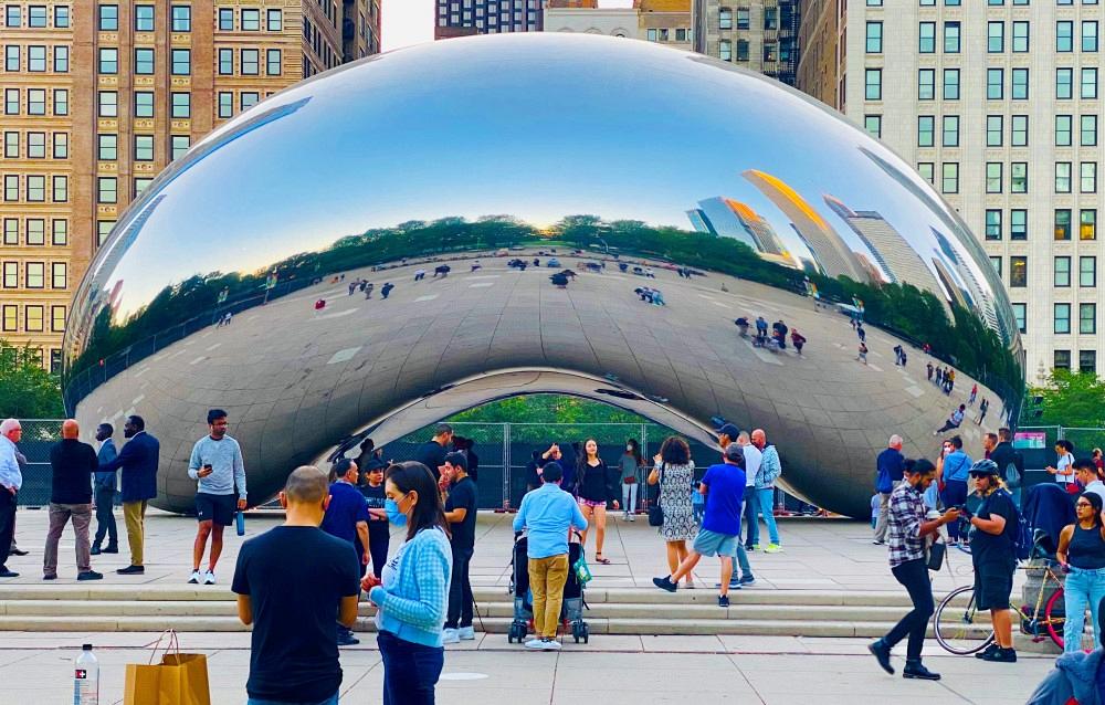
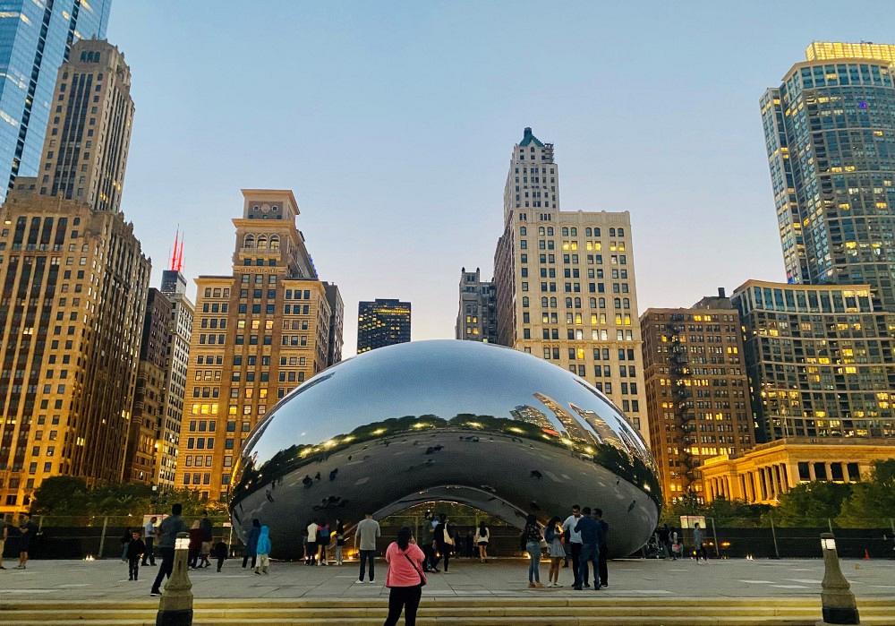
Anish Kapoor's vision for Cloud Gate sculpture in Chicago's Millennium Park was that it resemble liquid mercury, seamlessly reflecting the city around it. Achieving that seamlessness was a labor of love.
"What I wanted to do in Millennium Park is make something that would engage the Chicago skyline ... so that one will see the clouds kind of floating in, with those very tall buildings reflected in the work. And then, since it is in the form of a gate, the participant, the viewer, will be able to enter into this very deep chamber that does, in a way, the same thing to one's reflection as the exterior of the piece is doing to the reflection of the city around."
– World-renowned British artist Anish Kapoor, Cloud Gate sculptor
One could hardly guess by looking at the placid surface of the monumental stainless steel sculpture how much metal and mettle are below its surface. Sealed within Cloud Gate are the stories—five-plus years in the making—of more than 100 metal fabricators, cutters, welders, finishers, engineers, technicians, ironworkers, erectors, and managers.
Many worked overtime, performed shop work in the middle of the night, camped out on-site, and toiled in 110-degree temperatures in full Tyvek® suits and half-mask respirators. Some worked in gravity-defying positions, suspended from harnesses while holding tools and working on slippery slopes. All went a little beyond (and far beyond) so that the impossible could be made possible.
Materializing sculptor Anish Kapoor's ethereal floating clouds concept into the 110-ton, 66-foot-long by 33-foot-high stainless steel sculpture was the task of fabricator company Performance Structures Inc. (PSI), Oakland, Calif., and MTH, Villa Park, Ill. In its 120th year, MTH is one of the oldest architectural metal and glass structural design contractors in the Chicago area.
Achieving the requirements of the project would mine the two companies' artistic execution, ingenuity, mechanical know-how, and fabrication savvy. They customized and even created equipment for the project.
Some of the project's challenges arose from its oddly curving shape—an omphalus, or inverted belly button—some from its sheer enormity. Constructing the sculpture at separate sites thousands of miles apart by two different companies created transport and workstyle issues. Many of the processes that had to be done on-site were difficult enough to achieve in a shop environment, much less in thefield. Much of the difficulty arose simply because such a structure had never been created before; therefore, there was no reference, no blueprint, no roadmap.
Having in-depth experience creating shell structures, initially on ships and later on other art projects, PSI's Ethan Silva was uniquely qualified for the shell structure fabrication task. Anish Kapoor asked the physics and art graduate to provide a small-scale model.
"So I made a 2- by 3-meter sample, a very smoothly curved, polished piece, and he said, 'Oh, you did it, you're the only one who did it,' because he had been looking for two years to find somebody to do this," Silva said.
The original plans were for PSI to fabricate and construct the sculpture completely, after which the entire piece would be shipped south on the Pacific Ocean, through the Panama Canal, north up the Atlantic and down the St. Lawrence Seaway to a port on Lake Michigan, where a specially designed conveyor system would transport it up to Millennium Park, according to Millennium Park Inc. ExecutiveDirector Edward Uhlir. Time constraints and practicality forced those plans to change. So the curved plates had to be braced for transport and trucked to Chicago, where MTH would assemble the substructure and superstructure and join the plates to the superstructure.
Ultimately, the sculpture was to resemble liquid mercury, said to be the artist's inspiration.
Finishing and polishing Cloud Gate's welds to achieve a seamless appearance was one the toughest aspects of the onsite erecting and assembly tasks. The 12-step process concluded with a brightening rouge likened to jeweler's polish.
"And so we basically worked on that project, making those parts, for about three years," Silva said. "It was a major task. And a lot of that time was spent figuring out how to do it and working out the details; you know, just perfecting it. Our approach, using computer technology and good old-fashioned metalworking techniques, was a combination of blacksmithing and aerospace technology."
It was difficult to fabricate something very precisely that would be so large and heavy, he said. The largest plates were, on average, 7 ft. wide and 11 ft. long and weighed as much as 1,500 pounds.
"Doing all the CAD work and just creating the actual construction drawings for the piece was actually a big project in and of itself," Silva said. "We used computer technology to measure the plates and to accurately assess their shape and curvature so they would all fit together correctly.
"We did computer modeling and then divided the piece up," Silva said. "I utilized my experience with shell structures and I had ideas about how to divide up the shape to make the seam lines work so we would have optimum-quality results."
Some plates were squared, some were pie-shaped. The closer they got to the sharp transitions, the more pie-shaped they were, and the greater the radial transition. At the top, they were much flatter and larger.
Plasma cutting the 1/4- to 3/8-in.-thick 316L stainless steel plates themselves was tough enough, Silva said. "The real challenge was to get the mammoth plates to the precise-enough curvature. And that was done by very accurately forming and fabricating the rib-system framework for each plate. That way we could accurately define the shape of each plate."
The plates were rolled on a three-dimensional roller that PSI designed and built specifically to roll these plates (see Figure 1). "It is sort of a cousin to an English roller. We rolled them using techniques similar to fender-making," Silva said. Each plate was curved by moving it back and forth on the roller, adjusting the pressure on the rolls until the plate was within0.01 in. of the required dimension. The high level of precision required made it difficult to form the plate smoothly, he said.
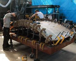 | 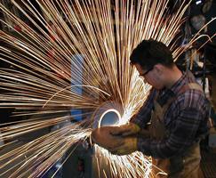 |
| Figure 1 Much of the equipment had to be designed or customized especially for Cloud Gate. PSI designed and built a three-dimensional roller to roll the plates smoothly and precisely. Each plate was curved by moving it back and forth on the roller, adjusting the pressure on the rolls until the plate was within 0.01 inch of the required dimension.(Photo courtesy of PSI, Oakland, Calif.) | Figure 2 The plates were grinded and polished to a mirror finish before they were shipped and assembled. (Photo courtesy of PSI, Oakland, Calif.) |
The welders then flux-core stitch-welded the curved plates onto the inner rib-system structures. "Flux-core is really a wonderful way to create structural welds, I think, in stainless steel," Silva explained. "It gives you a great-quality weld and it's very production-oriented and it has a good appearance."
The plates' entire surfaces were both hand-ground and machine-milled to trim them to the thousandths-of-an-inch precision needed so that they would all fit together (see Figure 2). Precision measuring and laser scanning equipment were used to check the dimensions. Finally, the plates were polished to a mirror finish and covered with a protective film.
Before the plates were shipped from Oakland, approximately a third of the plates and the base and interior structure were erected in a trial fit-up (see Figures 3and 4). Plate-hanging procedures were planned and some seam welding done to a few of the small plates to combine them. "So we knew it was going to fit when we were putting it together in Chicago,"Silva said.
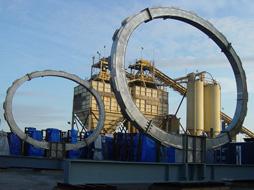 | 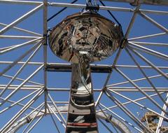 |
| Figure 3 The superstructure to which the plates would be attached started with O-shaped rings and a pipe truss system. (Photo courtesy of PSI, Oakland, Calif.) | Figure 4 A third of the plates, and the base and interior structure, were erected in a trial fit-up in Oakland before being shipped to Chicago. The erecting of the superstructure started with the "belly button." (Photo courtesy of PSI, Oakland, Calif.) |
Temperature, time, and truck vibration could have caused the rolled plates to relax. Not only were the rib grids designed to add stiffness to the plates, they also were intended to retain the plate's shape while in transit.
So, with the reinforcing grid on the interior side, the plates were heat- treated and cooled to release the material stresses. To further prevent damage in transit, cradles were made for each plate, and the cradles were loaded on containers, about four at a time.
Then the containers were loaded into semis, about four at a time, and were sent to Chicago, along with PSI staff to work with MTH's staff on the installation. One was a logistic person to coordinate shipping, and the other was a technical field supervisor. He worked alongside MTH's crew on a daily basis as well as to help to develop new techniques as needs arose. "He was certainly a very pivotal part of the process," said Silva.
At first it was MTH Industries' mission to anchor the ethereal sculpture to the ground and install the superstructure, and then also to weld the plates to it and perform the final grinding and polishing, with PSI providing technical direction, said Lyle Hill, MTH president. Completion of the sculpture meant balancing the artistic with the practical; theory with reality; time required with time scheduled.
Lou Cerny, vice president of engineering and the project manager for MTH, said what intrigued him about the project was its uniqueness. "There are things that happened on this particular project that, to the best of our knowledge, have never been done before, or really considered before," Cerny said.
But working on a first-of-its-kind required nimble, on-the-spot ingenuity to master unforeseeable challenges and answer questions that arose as the job progressed:
How do you mount 128 car-sized stainless steel plates onto a permanent superstructure while handling them with kid gloves? How do you weld the enormous curved bean without leaning on it? How do you penetrate the welds without being able to weld from the inside? How do you achieve a perfect mirror finish on stainless steel welds in a field environment? What happens if lightning strikes it?
Cerny said the first indication that this would be an unusually difficult project was when building and installation began on the 30,000-lb. steel substructure to support the sculpture.
Although the zinc-rich structural steel fabrications provided by PSI for assembling the substructure base were relatively straightforward, the site for the substructure was halfway over a restaurant and halfway over a parking garage, each at different elevations.
"So the substructure was kind of cantilevering, teetering over one point," Cerny said. "Where we were setting a lot of this steel, including the beginning of the plate work itself, we actually had to have a crane drive into a 5-foot-deep hole."
Cerny said they used highly complex anchoring systems, including mechanical pretension systems, similar to the types of things that are used in coal mining, and some chemical anchors. Once the steel substructure was set in concrete, a superstructure had to be erected, to which the shell would be attached.
"We started installing the truss system with two large fabricated 304 stainless steel O-shaped rings—one at the north end of this structure, and one at the south end," Cerny said (see Figure 3). The rings are held together with criss-crossing pipe trusses. The ring-core subframe is built in sections and field-bolted with welded reinforcements using GMAW and stick welding.
"So there's this big superstructure that no one ever sees; it's strictly for structural framing," Cerny said.
Despite best efforts to design, engineer, fabricate, and erect all the needed components for the project in Oakland, this sculpture was unprecedented, and blazing new trails always comes with burrs and scratches. Too, meshing the fabrication concepts of one company with those of another wasn't as simple as passing a baton. In addition, the physical distance between sites created delivery delays that made some on-site fabrication logical.
"Though the assembly and welding procedures had been worked out in advance in Oakland, the actual field conditions required adaptive ingenuity from everyone," said Silva. "And the union crew was truly great."
For the first several months, MTH's daily ritual was to determine what was needed for the day's work and how best to fabricate some members needed to erect the subframe, as well as some of the struts, "shock absorbers," arms, pegs, and pogo sticks needed to erect a temporary plate-hanging system, Hill said.
"It was a continual process, to design and fabricate on the run to keep things moving and get them out to the site quickly. We spent an awful lot of time sorting out what we had, redesigning and re-engineering in some cases, and then fabricating the needed parts.
"Literally, on Tuesday we'd have 10 pieces of something we had to have on-site Wednesday," Hill said. "There was a lot of overtime, a lot of shop work done in the middle of the night."
"Probably about 75 percent of the plate-hanging assemblies were fabricated or modified in the field," Cerny said. "On several occasions, we literally fabricated 24 hours a day. I would be at the shop until 2 or 3 in the morning, I'd go home, take a shower, and pick up material at 5:30 in the morning, still wet."
The temporary suspension system MTH used to assemble the shell was composed of springs, struts, and cables. All the joints between the plates were bolted together temporarily. "So the whole structure was mechanically attached, suspended from the inside, the 304 trusswork," Cerny said.
They started with the dome on the underside of the omphalus sculpture—the "belly button of the belly button." The dome was suspended from the truss using a temporary four-point hanging spring support system composed of hangers, cables, and springs. The springs provided "give-and-take" as more plates were added, Cerny said. Then the springs were readjusted based on the weight each plate addedto help balance the entire sculpture.
Each of the 168 plates had its own four-point hanging spring support system and so was individually supported as it was put into place. "The idea was to not overstress any joint, because these were put together to a 0/0 clearance," Cerny said. "If one plate hit the plate below it, it could cause buckling and other problems."
As a testament to the accuracy of PSI's work, the fit-up was so good, the gaps were nearly nonexistent. "PSI did a tremendous job of fabricating the plates," Cerny said. "I give them all of the credit for that, because in the end, it actually fit. The fit-up was excellent, which to me was amazing. We're talking about, literally, thousandths of an inch. The plates came together with a closededge."
"When they were done fitting it up, many people thought it was finished," Silva said, not only because the seams were tight, but also because the fully assembled Piece, with its highly polished, mirror finished plates, had emerged in its role to reflect its surroundings. But the butt joint seams were visible, and liquid mercury does not have seams. Also, the sculpture still had to be fullyseam-welded to retain its structural integrity for all posterity, Silva said.
Completion of Cloud Gate had to be put on hold during the park's autumn 2004 grand opening, so the omphalus was spot-GTAW, and that's how it stayed for months.
"You could see little brown spots, which were TIG spot welds all the way around the structure," Cerny said. "We started putting the tent back up in January."
"The next big fabrication challenge of this project was to weld the seams without losing the accuracy of the shape due to weld shrinkage distortion," Silva said.
Plasma welding provided the strength and rigidity needed, with minimal risk to the plates, Cerny said. A 98 percent argon/2 percent helium mixture worked best to reduce the scaling and enhance the fusion.
The welders used a keyhole plasma welding technique using a Thermal Arc® power supply and a special tractor and torch assembly developed and used by PSI.
"A small mechanical bug runs on a rubberized track that holds the plasma torch and the wire-feeding mechanism. The plasma torch cuts a keyhole through the two plates. As it cuts the plate, a wire-feeding mechanism behind the torch in the heat zone area feeds the wire, and the wire melts and becomes the weld joint," Cerny explained.
The semiautomatic system uses a rubberized track with suction cups so that it conforms to the shape of the structure. "As you move around a particular seam, and the seam changes in radius, it also changes—it also curves sideways, not just straight in two dimensions," Cerny said.
"The welds had to be full-penetration welds, but we had to weld from one side only—all from the exterior," he continued. To achieve full weld penetration, the welders used a custom-formed aluminum channel, or chamber, on the back side that straddled the joint being welded. It was held in place and pressed against the joint by a series of Robin clamps. It was plugged with putty where necessary to prevent shield gas escape. The channel was flooded with inert gas so that the gas literally was being fed into the joint from the inside face, Cerny explained.
"We're not talking about new technology—we're talking about using the technology in a field condition under strange circumstances and modifying it to work, really," Cerny said. "The heads were modified, cut at certain angles, and everything else was changed slightly. We did a lot of experimentation to get it to work, because it was all-position welding within the same run—meaning it's right in front of you, vertically up, vertically down, and overhead. So you're constantly adjusting your gas feed, your wire feed speed, how fast you're traveling It's something that the guys had to develop as they were working with it. There is no book that tells you that, unfortunately."
"The nerve-racking thing for the welders, I think, was they knew if you screw up and blow holes, there's a lot of repair," Cerny said. "If you don't get full-penetration welds, you cut it back out. We were very fortunate; they did a very good job, and they handled it pretty quickly. Essentially we did it in the time we said it would take, and at the level of quality we were hoping for."
"Because this was a first-time project, a new process, and a new product, we wanted to err on the side of caution," Hill said. "For instance, we originally followed a recommendation as to how to preload the plates, as we refer to it. The theory is you push out the two edges where these two planes meet, actually force the edges out high, or proud, as they are welded into place, and then underheat, they shrink back. You would then grind the joint down into plane. You never want to have a concave joint.
"Well, guys in the field pointed out that initial assumptions as to how the steel would react during welding were way off. The shrinkage during the plasma welding technique ended up being almost nonexistent. So we were pushing them out 0.0015 inch, and then they were standing 15 thousandths high. So we started pulling it back. There was a certain amount of trial and error."
Once all the plates were fully in place and the exterior plate welding was completed, permanent weld-ups had to be done on the inside.
The third and final phase of the project was the final grinding and polishing.
"The goal was to eliminate the visibility of the seam," Cerny said (seeFigure 5). "It's not just that you're trying to make this thing disappear under some amount of light. It's fully exposed under the brightest of lights available—the full sun at high noon. People can walk up to it from every possible angle. And we were more than a little concerned."
Working on a unique, never-done-before project comes with risk. "When we were asked to do the plasma welding and polishing, internally we had a little bit of a debate over whether or not we wanted to do it," Hill said. "We had peers in the industry—both guys who fabricate only in-house and companies that do field fabrication and finishing—tell us, 'You're not going to be able to achieve a mirror finish after welding stainless steel. You will have discoloration or a rough surface, most likely both.'
"We were in a tough situation because it's one of those projects that we had a fair amount to gain if it turned out well, and a tremendous amount to lose if it didn't," Hill said. "I had a lot of sleepless nights during the course of the job."
The weld finishing was a 12-step process, explained Cerny, beginning with rough grinding the weld close to the existing surface using 60-grit zirconium paper on a circular belt. To grind material out of the joint so it would blend with the surrounding areas without gouging, all subsequent sanding was done with semiautomatic belt sanders with wheels on them that would "ride" the material outside of the joint.
"The wheels had adjusting screws on them, and we would set the height or depth of the belt and keep adjusting them until we got to the surrounding surface height and everything was blended to the same level of finish," Cerny said.
From there, the finishers used a special grade of 400-grit ceramic sandpaper, called a type CF-Trizact™ "It's something you don't really see in our industry; it's usually for a surgical instrument. But it works very well on stainless," Cerny said.
3M worked with them to develop some new belting systems to make the finish very bright before the final polishing phase, he said.
"They allowed us to work on some that aren't on the market yet," Cerny said. "3M also came up with probably a couple dozen sanding products, and we took it down to about six that worked for us, so most of this was done with a belt machine and 3M products."
Still, you can lead an omphalus to sandpaper, but you can't make it shine.
"It was a lot of trial and error," Cerny said. "You're grinding and polishing welds on a curved surface, and on relatively thin stainless steel, which is very unforgiving. You can't attack it too aggressively, because if you gouge it, if you get a ripple in it, or you burn through it, you're going to spend an inordinate amount of time reshaping that piece to get it back into proper curvature, and trying to replace one of those plates would be a massive effort."
Avoiding distortion while polishing the welds was the toughest part of the process, Cerny said. "That mirror- finish surface is very, very susceptible to looking like a funhouse mirror if it isn't exactly flush, especially when you've got buildings around you with straight lines.
"Which means the guys who did the finishing work really had to sculpt it. They had to actually use a marker to draw a grid across the joint and the surrounding area and then bend a batten strip around the curvature. And they looked for any high spot or a gap and ground those until they disappeared.
"You could start out with a weld seam only about a half inch wide and end up with an area 18 to 20 inches wide, blending that joint. It's kind of like what autobody people do, but with stainless steel, it takes forever to do that. There couldn't be any abrupt changes in the surface."
To achieve the gleaming, highly polished, reflective mirror finish, the finishers used a kind of jewelers' polish, a waxy substance called a rouge. Three types of rouges contain three grades of abrasives.
"A lot of the rouges that are capable of taking the polish from a semifinished surface to a mirror finish—we call them cutting rouges—also have a fair amount of abrasives in them, which means they literally cut the stainless. Our problem was, they also added distortions, waves. So we only used the final 800-grit rouge, a lubricant, for brightening and to remove the final scratches," Cerny said.
"Everyone will tell you that if you skip a step, you have to go back," Cerny added. "Because we had to do this on a co-production basis—we had 24 or 25 people working at once just on the outside—we had to make sure all the steps were taken. We didn't polish a 3-foot square all the way to mirror and then move over. We would do a certain step on large areas of the surface and then do the next step.
"But the target—and everybody's got crossed fingers—is that when we get to the next step, everything goes OK."
MTH had put up a 60- by 100-ft. custom tent, first to avoid disruption from the winter while constructing the substructure and assembling the ring core, and then to confine the welding gases.
Because grinding stainless steel produces nickel chromium and hexavalent chromium dust, the tent was also needed to enclose the structure to keep the dust and shavings from getting around the general public area.
Cerny described the difficult working conditions inside the tent during the finishing process: "You have clothes on, then you put on a full-body Tyvek® suit, which doesn't breathe, then a hood. Then you put this half-mask respirator on your face, and gloves, and then you put a shield over your face, while it's 90 degrees outside." The temperature in the top of the protective tent could exceed115 degrees.
"And now you're working on this structure that you have no way to hold yourself onto. You're literally climbing around on ropes and everything else you can, and holding a piece of equipment. Essentially we had suspension harnesses next to the structure and on the entire upper half of the structure on the outside. You're changing belts, you're adjusting machines, while you're on a sloping surface that's really slippery. And at the same time, you're trying to work. You've got all this dust being kicked up. It was a nightmare. So you can imagine how difficult it was to be productive," Cerny said.
To protect the welders and finishers, MTH ran eight HEPA filters continuously during the welding process and monitored the air quality throughout the welding and finishing stages through a computer hook-up back in the office, Hill said. "We were very concerned about the health and safety of the guys.
"We also had OSHA on-site," Hill continued. "We went by the book for exposure levels and testing. Our guys were welding and grinding, and they were working under some really lousy conditions. More hexavalent chromium is released during the welding process than the grinding, but with grinding, we had so many more months of exposure. At least with this structure, it was a bigger concern than welding."
For both PSI and MTH, the Cloud Gate project consumed more time than expected.
"The timing was really upon us to get it done," Hill said. "The project took almost two years and that really hurt, because we had to turn other work down.
"We were physically limited as to how many people could work at once productively. They would physically be on top of each other. At one time, we had 24 of our best field crew down there. We've had some of the best architectural ironworkers in the country tied up on this thing," Hill said.
"I think we reached the point where, OK, you're in it, and you've committed to it, so you're going to have to finish it."
The final finishing on Cloud Gate has just been finished, and so it is officially completed. So, has the heavenly mission been accomplished? Does Cloud Gate's skin resemble liquid mercury? The proof is in the reflection. The reader will have to inspect the sculpture and judge. At least one observer has described Cloud Gate as a people magnet—tilt their heads, and invariably they are drawn under its 12-ft.-high arch to peer at their reflections in its 27-ft.-high vortex.
Hills, Cerny, and Silva had glowing remarks for the workmanship and craftsmanship of everyone involved.
"The guys we had on the job were phenomenal," Hill said. "We had three or four guys down there that are just mechanical geniuses. And a couple of the ironworkers here in the shop helped modify the equipment."
"Most of the fabricators have adopted the attitude that this is not just their job, this is something their kids and grandchildren will be able to look at," Cerny said. "They wanted to do it right. They really took this much more personally than any other piece of work I've seen them do."
"When we first met MTH, I was very impressed by their can-do attitude, technical sophistication, and practical approach to solving problems," Silva said.
Silva added, "I think that the artwork is magnificent. It's nice to work with something that's going to be around for a long time. My children and my grandchildren can go see it. I've really enjoyed that aspect of it."
Cerny concurs. "This will outlive every one of us who's worked on it. It'll be there for generations to come."
What's next? "As I go on in life, building Cloud Gate will always be one of the milestones in my career," Silva said, adding that this experience is leading him in exciting and satisfying new directions.
"Now we'll look for some other problem to deal with," Cerny said. "I don't know that I'd be looking forward to doing another one of these right away, though," he said with a laugh.
Time may tell if he will or not. Rumor has it that another feature has just recently been proposed for Millennium Park—a shining "samurai sword" bridge leading from the center of the park to the third floor of the adjacent Art Institute. With a mirror finish. Jewelry polish, anyone?
Forming two structural and fabrication wonders
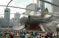
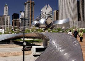
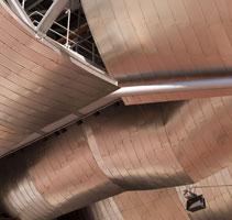
Both of the Frank Gehry-designed stainless steel structures in in 24.5-acre Millennium Park, Chicago, are identifiable by his signature "ribboning" designs. In fact the two structures are integrated; the sinuous walkway approach of the Millennium BP Bridge functions as a visual and sound barrier from Columbus Drive for the Jay Pritzker Pavillion, an outdoor concert venue. Jay Pritzker PavilionThe 120-foot-high Jay Pritzker Pavilion is a structural and fabrication wonder. The billowing brushed stainless steel ribbons that frame the proscenium opening are supported by the roof trusses of the pavilion below, which cantilever out a remarkable 130 ft. from the stage. Designing and fabricating the ribbons were a marriage of illusion and practicality, according to John Zils, of architect engineer firm Skidmore, Owings & Merrill LLP, Chicago, the senior structural engineer for the pavilion as well as the BP Bridge. "We decided to use straight sections and segment them to create the illusion of curvature," Zils said. "In other words, there actually are no bent members in those ribbons," Zils said. The framing sections are set up on a 9- by 10-ft. grid to form the rough curvature. The verticals are wide-flange sections and the horizontals are square tubes, prefabricated in the shop in straight sections. The angle change takes place at nodal points on the grid to follow the curvature, Zils said. "So when the stainless steel cladding was attached, it actually had the exact curvature that Gehry was looking for." The backup structure was prefabricated into segments which were trial-fitted and then brought to the site and assembled into larger sections. Prefabricated aluminum backup panels were then mounted to the backup structure with a bolted connection. Then the stainless steel "shingles" were attached mechanically with clips to the backup panels. "So each one of the metal ribbons might have three or four prefabricated structural sections that were then erected in pieces," Zils said.
Fabricating Space Out of AirThe stage area is connected to an overhead trellis of crisscrossing steel pipes. The matte-painted, tubular trellis made of arched, sectionalized hollow structural sections is a bit of an abrupt divergence in shape and sheen from the glistening ribbons framing the proscenium—in some ways resembling the tubular trusses supporting the ribbons more than the ribbons themselves. But it serves a dual, practical purpose, both columnlessly defining the 7,000-person lawn seating area and structurally supporting the state-of-the-art sound system, said to mimic the acoustics of an indoor concert hall. "Frank Gehry wanted to see an honest structure, Zils said. Considered independently, the open-air "acoustical canopy," is, itself, artful. Somehow, 570 tons of steel manage to sprout and arch gracefully from pylons flanking an area roughly the size of two football fields—625-ft. long by 325-ft. wide. The 12-, 14-, 16-, 18- and 20-in.-diameter hollow structural sections, fabricated by Acme Structural, Springfield, Mo., that lace the area diagonally and are fitted into TYK joints at precisely engineered, designated nodal intervals. Acme Structural cut the pipe and fabricated and welded the TYK joints, or nodes, where the pipes intersect. Obviously, the welded intersections were critical. Each of the pipe sections was rolled at one of five different radii—ranging from a sharp 100 ft. radius to a shallow 1,000-ft. radius—on enormous Roundo three-roll benders by Chicago Metal Rolled Products, (CMRP) Chicago, the company Acme Structural hired to roll-bend the pipes. The finished look was critical, so there could be no scratches—not even as shallow as a fingernail deep—in the pipe, CMRP president George Wendt said. Not only did the company have to use TLC in handling the pipes, using nylon slings, for example, it had to roll them in a way that would minimize damage in-process. The fabricator had to develop custom tooling—sets of rolls—to fit each diameter, aswell as the process to curve these large pipes cold to architectural exposed structural standards (AESS). "We suggested that it would be easier to fabricate and less expensive if we bent the pipe on one planee and changed the radii at the point where each of the pipes cross each other at these nodal junctions," Wendt said. "It's a little more complicated than it looks. Two arched pipes spring up from each pylon. One arches out at a flat, low curve, and the other one arches at a higher curve. They tilt so they end up two or three pylons on the other side of the field. They meet the other pipes and crisscross them at the same plane at different angles."So it was a major breakthrough from a fabrication standpoint, and a big cost-reduction standpoint," Zils said.
BP BridgeThe other Frank Gehry-designed feature in Millennium Park is a 925-foot-long, sloping pedestrian bridge that meanders seemingly aimlessly but that actually functions as a link to Grant Park and Lake Michigan as well as a sound barrier for the pavilion. Other than its hardwood deck, it is entirely clad in stainless steel panels. Zils said a major challenge was achieving Gehry's shape, configuration, and low-profile (1-to-20 ratio) requirements. "We had to figure out a way to span over Columbus Drive, a major thoroughfare with a certain minimum clearance, and yet create a bridge that had quite a thin profile and a curvilinear shape to it," Zils said. "The structural depth that we had to work with kept getting squeezed. That's part of the reason for the very long walkway approaches, to create that gentle slope." Three different structural systems comprise the bridge structure, Zils explained: Structural steel cantilever truss sections extend from those two concrete approaches over the edge of the roadway. They are constructed of two-inch-thick, 20-in.-round structural steel pipe and connecting members—10- and 14-in.-wide flange sections—welded together in a cantilevered truss configuration. Connecting those cantilever sections is a 6-ft.-wide, 3-ft., 6-in.-deep structural steel rectilinear box girder structure with an arched underside. This girder is the member that carries the load. It is built of 1-1/2-in.-thick plate on the vertical, and the horizontal top and bottom plates vary in thickness. It is supported by the juncture points at the ends of the cantilevers, as well as by an independently supported concrete center pylon in the middle of Columbus Drive. The curvature of the bridge is created not only by the serpentine layout but also by "skirts" flaring horizontally from the bridge's sides. Skirts. What actually composes the bridge's skirts are secondary structures welded to the box girder and cantilevered widthwise, Zils explained. Top and bottom flange plates 1-1/2 in. thick and 10 and 8 in.-wide and other fabricated shapes act as outrigger arms on 10-ft. centers. Horizontal members connected between the outrigger arms act as horizontal girts. An aluminum backing panel spans between the girts. Then the stainless steel cladding is attached mechanically to the backing panel. This skirt forms the sloped edge of the bridge. Permasteel is a Cladding Technologies, USA, Windsor, Conn., the project subcontractor that fabricated all the steel components for the skirt, underside and walkway, produced 9,406 stainless steel panels. The panels are fabricated as shingles, designed to shed water from rain or snow like fish scales. Arch. In addition, the underside of the bridge arches over Columbus Drive—achieved by a combination of the structural curvature of the cantilevered sections and box girder, and curved studs that follow the arched shapes. Radius Track, Blaine, Minn., manufactured the 132 curved steel studs that formed the final curvature of the "underbelly" structure. The 0.054-in.-thick (16-ga.) G90 galvanized curved steel studs and beams are attached to the heavy steel plate superstructure, or "red iron." Standard aluminum panels and saddle clips were fastened to the studs to help create the curved surface. The stainless steel shingles are mechanically attached to the curved studs./p> Permasteelisa used CATIA® to create files of XYZ coordinates to send to Radius Track that indicated precisely where and how the hollow, roll-formed studs were to be curved. CATIA modeled the varying degrees, locations, lengths of bends and produced a numerical control file that was sent directly to Radius Track's computer numerically controlled machine that curves and fabricates the studs. Separate files indicated where the mounting holes had to be drilled for cross braces between the curved stud beams. Radius Track's proprietary crimping and curving method reduces the time required to curve studs, according to president Chuck Mears. The other commonly used method—cut and strap—consumes more time because the studs have to be to cut almost all the way through, pivoted, and reattached with fasteners, he said. One-Weekend Window of Opportunity. Intensifying the pressure created by the challenges inherent in the project was that only a short window of opportunity existed for the erecting and installation of the cantilevered sections and box girder. Columbus Drive would be closed only one weekend. "So one of our requirements was that these portions of the bridge be assembled and mocked up in the shop so that the fabricator could then check all his alignments before he shipped everything out here to the site," Zils said. "Doing these trial fit-ups in the shop was crucial." |

The Fabricator is North America's leading magazine for the metal forming and fabricating industry. The magazine delivers the news, technical articles, and case histories that enable fabricators to do their jobs more efficiently. The Fabricator has served the industry since 1970.
start your free subscription
Easily access valuable industry resources now with full access to the digital edition of The Fabricator.

Easily access valuable industry resources now with full access to the digital edition of The Welder.

Easily access valuable industry resources now with full access to the digital edition of The Tube and Pipe Journal.

Easily access valuable industry resources now with full access to the digital edition of The Fabricator en Español.
In this episode of The Fabricator Podcast, Caleb Chamberlain, co-founder and CEO of OSH Cut, discusses his company’s...