


A grand unifying theory of press brake bending: Part II
For success in large-radii bending, follow these five steps
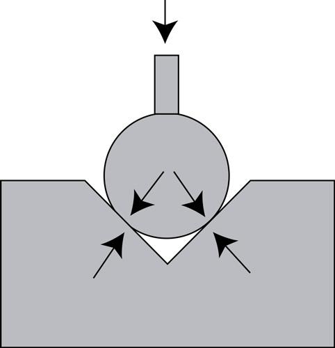
Figure 1
If you put a large round punch in a standard V die, it will
crash into the sides of the die. This leaves no easy way to
deal with springback.
Last month I introduced a new way of predicting the inside bend radius that can help you get your bend calculations ever closer to perfection. To do this, we’re moving away from some traditional definitions and formulas. Instead of terminology we’ve used in the past for sharp, radius, and profound-radius bends, we’re working with new terms and definitions as follows:
- Sharp bends have a specified inside radius that’s generally 63 percent or less of 60-KSI cold-rolled steel. (For more on this, see “How an air bend turns sharp” on www.thefabricator.com.)
- Perfect bends have an inside radius that’s between 63 percent and 125 percent of the material thickness.
- Radius bends have an inside radius that’s greater than 125 percent of the material thickness.
I’m calling this the Grand Unifying Theory of radius, bend deduction, and die selection, and for this installment, we’ll start with the last category: the radius bend.
Die Considerations
Because of their radius-to-material-thickness relationship, radius bends have more springback. The greater the inside radius, the greater the amount of springback. This radius-to-material-thickness relationship varies widely for radius bends, as does the amount of springback. To accommodate all this, both punches and dies have included angles ranging from 90 to 180 degrees.
Our first concern is to ensure the punch angle matches or has a lesser included angle than the die to avoid crashing the tooling. A true V die has a 90-degree angle; any die with an included angle less than 90 degrees is an acute-angle tool.
You need clearance between your punch and die angle to accommodate for the springback. (Although we’re focusing on air bending here, you also need this clearance when bottoming.) Finding a tool set with angular clearance isn’t a problem for small-scale radius bends (that is, applications involving thin material and narrow punch radii), where you can still have angular clearance between the V die and punch angle.
But for forming very wide-radius bends, problems arise. Figure 1 shows a 90-degree round punch in a 90-degree V die. If you put this large punch into any V-die angle, it will crash into the sides of the die. The only way to deal with this is for the operator to clamp the material between the punch and die and use muscle power to force the material into position—a difficult and very inconsistent operation.
This is why V-style dies in excess of 1.000 inch should be relieved—that is, have material removed from the die face to avoid the interaction between the punch and die, as shown in Figure 2. V dies more than 1.000 in. wide may also have included angles of 30, 45, 60, 73, 78, 80, and 85 degrees. These narrow angles help force the material around the punch nose and compensate for springback. The relieved V die allows a 90-degree punch to enter a die space with a 73- or 78-degree included angle and still not interact.
This does create the phenomenon known as multi-breakage, where a secondary radius forms. This is the leading radius that precedes the punch radius when the bend angle exceeds 90 degrees complementary. The greater the complementary bend angle, the smaller the leading radius (see Figure 3).
To find the correct V-die width for radius bends, you can multiply the outside bend radius by 5. To find the outside bend radius, add the inside bend radius to the material thickness. That is:
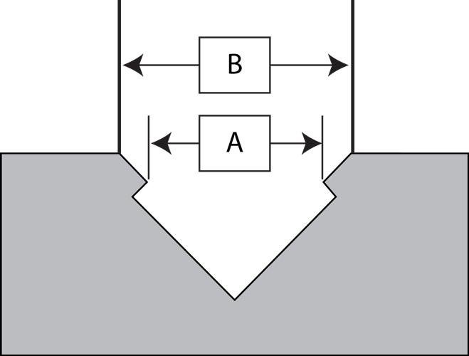
Note that if you’re using relieved dies, the die width is measured where the relieved section starts, as marked by dimension A in Figure 4. If you have an outside radius of 0.394 in., your optimum die width would be: 0.394 × 5 = 1.970 in. This means the perfect die would be 1.970 in. in width as measured from dimension A. Because the depth of penetration required to compensate for springback is great, the bend will pivot at A.
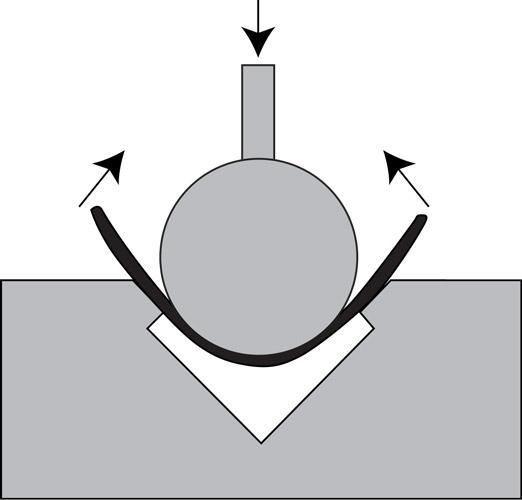
Figure 2
Relieved dies have material removed from the face. This
allows the punch to overbend for springback without
crashing into the die.
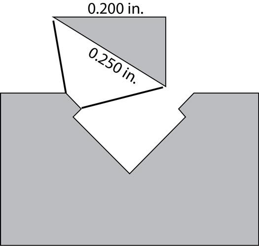
You’ll need to account for the difference between A and B—the corner offset—when making your bend calculations. If measuring the actual tool isn’t an option, and you know the tool angle and face length before the relieved section (that is, the length between where the die shoulder ends at B and the bend pivot point at A), you can use a little right-angle-triangle trigonometry.
Say you’re working with a V die with an angle of 73 degrees; you know that the face length before the relieved section is 0.250 in. To calculate the corner offset, you can work the following formula, based on a right-angle-triangle trig equation (see Figure 5):
Considering all this, let’s run a sample bend calculation for a radius bend. We’ll split this calculation into several parts. First, we determine the optimum die width to get us as close as possible to the desired inside radius. Second, we determine the tonnage requirements. Third, we’ll calculate the springback, so we know how many degrees we’ll need to overbend. Fourth, we’ll use online calculators to get our inside radius prediction as close as possible. And fifth, we’ll incorporate the difference between the “bent-to” and bend angle (that is, the springback factor). The springback formula in the second step requires metric values, so we’ll list everything in both millimeters and inches.
1. Determine the Optimum Width of a Relieved Die
2. Determine Tonnage Requirements
Next, be sure the job’s tonnage requirements do not exceed the limits of your selected tooling and press brake. In this example, we’ll assume that the job does not exceed tonnage limits, but for more on this, you can refer to the “4 pillars of press brake tonnage limits,” available at thefabricator.com. To review, here are the basic formulas:
3. Calculate the Springback
Here we calculate the springback using a formula introduced last month. This formula requires you to convert inches to millimeters. In this example, we’re working with our baseline material, 60-KSI-tensile cold-rolled steel. To incorporate other materials, you’d multiply the result by a material factor. For instance, if you had 120-KSI material, you’d divide 120 by 60 and get a material factor of 2.
We now can estimate that the metal will spring back 6.74 degrees after bending. This means that the “bent-to” angle—the angle we reach before the punch releases pressure and the metal springs back—is 90 – 6.74, giving us an included angle of 83.26.
4. Calculate the Radius
Next, we need to calculate the true outside radius of the bent-to angle of 83.26. To simplify the math, we can turn to www.handymath.com, where you can click on “The Complete Circular Arc Calculator” and enter the values for die width calculated in Step 1 (called the “Width of Arc” in the calculator) and included bent angle (called the “Angle Subtended by Arc”). From this we’ll uncover the outside radius, equivalent to the “Height of Arc” variable on the calculator. Note that the die width should be the measurement of dimension A in Figure 4. Also be sure all units in the calculator are in inches.
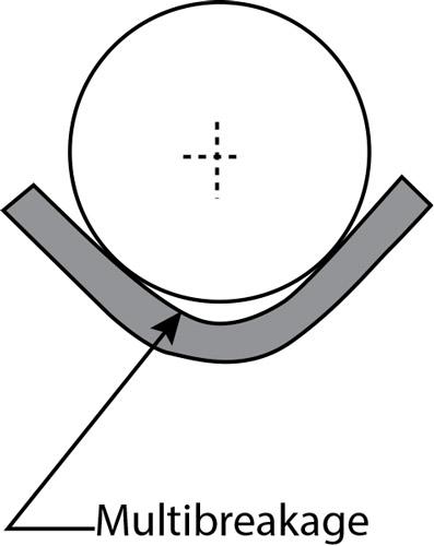
Figure 3
Overbending is necessary to overcome springback. In
large-radius bends, however, this creates the phenomenon
known as multibreakage, where a secondary leading
radius forms. The greater the complementary bend
angle, the smaller the leading radius caused by multibreakage.
5. Incorporate the Springback Factor
This outside radius value isn’t our final value, though, because as the workpiece springs back from 83.26 degrees included to 90 degrees, our radius changes as well. To account for this, we need to account for the difference between the bent-to angle (the angle the brake overbends the workpiece to overcome springback) and the final bend angle after the workpiece springs back. To do this, we divide the included bent-to angle value by the included bend angle value to uncover the springback factor, which we then multiply by the original radius.
If you follow the steps outlined here, you get an inside radius calculation that’s about as close as you can get. Insert this value into your bend functions formulas (outside setback, bend allowance, bend deduction) or software, and you’ll find that your bend calculations are closer than ever.
Effects of Small and Large Included Bend Angles
Notice that if you go back to the handymath.com online calculator and enter smaller included bent-to angles over the same 3.537-in. die width, the radius gets smaller relative to the punch radius. At 60 degrees included, the outside radius is 0.47387 in., while at 45 degrees included the outside radius is only 0.35178 in. This occurs because of the multibreakage effect described earlier.
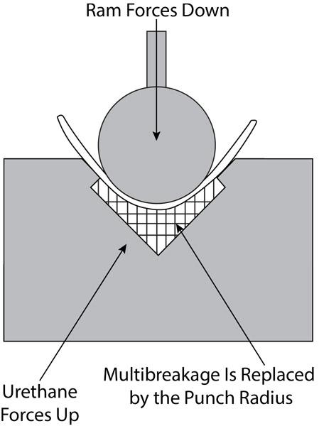
You can account for this multibreakage by designing your parts around available tools, or by designing a tool to produce a specific radius, knowing that the multibreakage effect is present. It’s also possible to “back up” the bend by placing a urethane pad at the bottom of the die (see Figure 6). The pad should have a low to medium durometer rating and be at least 10 times the volume of the penetrating punch and material. The pad will force the material against the tool and create a radius equal to that of the tool, less the bend/bent-to factor.
Open angles (that is, large included angles) have the opposite effect on the radius. When your bent-to angles are more than 90 degrees included, you will produce a radius that’s greater than the radius of the punch.
The Next Chapter: Aircraft Tooling
The example detailed here involves a relieved V die, but V dies aren’t used for every application. Another style of die is called the channel die, which is commonly used in the aircraft industry. We’ll cover this topic in detail next month.
After that, I’ll conclude by reviewing all the steps discussed during this series—from determining sharp bends and calculating springback to incorporating the parabola effect and running the bend functions. Ultimately, this Grand Unifying Theory of bending should help you overcome any bending challenge that comes your way.
Steve Benson is a member and former chair of the Precision Sheet Metal Technology Council of the Fabricators & Manufacturers Association International®. He is the president of ASMA LLC, 2952 Doaks Ferry Road NW, Salem, OR 97301, steve@theartofpressbrake.com. He also conducts FMA’s Precision Press Brake Certificate Program, which is held at locations across the country. For more information, visit www.fmanet.org/training, or call 888-394-4362. For more information on bending, check out Benson’s new book, The Art of Press Brake: the Digital Handbook for Precision Sheet Metal Fabrication, ©2014, available at www.theartofpressbrake.com.
About the Author

About the Publication
subscribe now

The Fabricator is North America's leading magazine for the metal forming and fabricating industry. The magazine delivers the news, technical articles, and case histories that enable fabricators to do their jobs more efficiently. The Fabricator has served the industry since 1970.
start your free subscription- Stay connected from anywhere

Easily access valuable industry resources now with full access to the digital edition of The Fabricator.

Easily access valuable industry resources now with full access to the digital edition of The Welder.

Easily access valuable industry resources now with full access to the digital edition of The Tube and Pipe Journal.

Easily access valuable industry resources now with full access to the digital edition of The Fabricator en Español.
- Podcasting

In this episode of The Fabricator Podcast, Caleb Chamberlain, co-founder and CEO of OSH Cut, discusses his company’s...
- Trending Articles
1
Capturing, recording equipment inspection data for FMEA

2
Tips for creating sheet metal tubes with perforations

3
Are two heads better than one in fiber laser cutting?

4
Supporting the metal fabricating industry through FMA

5
Omco Solar opens second Alabama manufacturing facility
