


Six steps for selecting the right die for press brakes
What inside bend radius you can achieve hinges on tonnage requirements and available die-opening widths
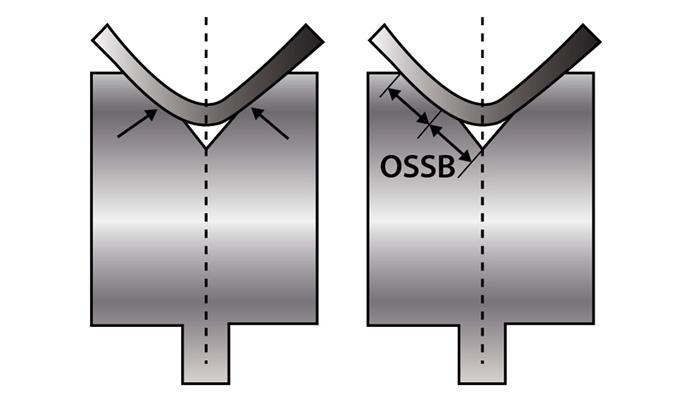
Figure 1
To get the most out of your tools, the tangent
of the bend, where the radius starts, ideally should be
halfway down the die face. In this situation, half the die
face is equal to the outside setback (OSSB), the distance
from the outside mold line (planes that run parallel to
the workpiece) to the tangent point of the bend.
A Question Regarding Selecting a Die for a Press Brake
Our fabrication department is documenting standard processes to select the correct die and punch combination to produce the desired results when air bending. We want to achieve a 90-degree bend for a 0.0751-in.-thick piece of 304 stainless steel with an inside bend radius that’s also 0.0751 in. There’s the 20 percent rule, and then there’s the 8x material thickness rule. How should I apply these rules to select a die opening?
Answered by Our Experts
The 8x rule is an age-old rule of thumb based on 60,000-PSI-tensile cold-rolled steel that states it’s best practice to choose a die-opening width that’s eight times the material thickness. You generally get the best working results when working with the 8x rule. You ease forming and attain bend angle stability while working within tonnage requirements. You will find you can produce an inside radius approximately equal to the material thickness.
Still, “8x” is only a label, and the factor can increase or decrease with the material thickness. Sometimes the die-opening width equals 6x material thickness, other times 10x or 12x. The 8x rule is a good rule of thumb that keeps the tonnages low and the parts stable, at least to a point. But, unfortunately, it really doesn’t take different material types into account.
The 20 percent rule defines the floated inside radius in an air form over a given die. Unlike the 8x rule, the 20 percent rule can be factored for material type. In 304 stainless steel, the inside radius will be 20 to 22 percent of the die-opening width; for cold-rolled steel, the inside bend radius will be 15 to 17 percent; and for 5052 H32 aluminum, the inside bend radius will be 9 to 11 percent. You start with the median value (in the case of 304 stainless, this is 21 percent), then adjust if needed.
The 20 percent rule simply describes the resulting inside radius when air bending, and it’s used to calculate bend deductions. However, it usually isn’t a means of developing a die opening, because it doesn’t take into account springback or tonnage limits.
For your stainless steel job, you could rewrite the 20 percent rule formula—Width of die opening × 21 percent = Inside bend radius—to read Inside bend radius/21 percent = Width of die opening. This would give you: 0.075 in./0.21 = 0.357-in. die-opening width. But again, this does not take into account springback or tonnage limits, and it could seriously overload the press or the tooling. This is small for a die opening, and tonnage should be a consideration.
To achieve a certain radius, you need the right tooling and press brake. Ultimately, available die-opening widths in your tooling library, as well as tonnage capabilities of your tooling and press brakes, will determine the inside bend radii you can achieve when air bending a given material type and thickness. A tooling selection procedure for air bending should include the following:
1. Ensure that the specified inside bend radius is not less than the minimum sharp bend radius. If it isn’t, the inside bend radius can’t be achieved physically, short of stamping or bottoming. That’s because, when the bend turns sharp, the punch starts to dig a ditch into the material. For mild steel, a bend usually turns sharp when the inside radius reaches about 63 percent of material thickness. (For more on sharp bends, see How a bend turns sharp.) In your case, of course, you’re looking to achieve a ratio of 1-to-1 for material thickness to inside bend radius, which is certainly achievable, as long as your tooling and machines can handle the tonnage requirements.
2. Select the die opening. When it comes to any kind of machine, you generally do not want to overuse or underuse it. You get the most out of the machine at half of the maximum working value. That being said, isn’t the combination of the die, punch, and material really a “machine”? Of course it is. So what is half the working value of a die? Under perfect conditions, that point occurs halfway down the die face, as shown in Figure 1.
To find the geometrically perfect die opening—one in which the bend occurs halfway down the die face—use the following formula: (Outside bend radius × 0.7071) × Factor = Perfect die opening. (Editor’s note: For more detail behind this formula, visit www.thefabricator.com and type “Finding the perfect die opening” in the search bar.)
To calculate your outside bend radius, add the desired inside bend radius to the material thickness. So in your example, you would add 0.075-in. inside radius to the 0.075-in. material thickness and get an outside bend radius of 0.150 in.
The factor in the formula is a multiplier, and a multiplier of 4.0 would give you a value as close to geometrically perfect as possible, practically speaking, but with no allowance for springback. To account for springback, increase the multiplier slightly. In material thicknesses less than 0.125 in., a realistic working multiplier is 4.85. In material between 0.125 and 0.250 in., the multiplier is 5.85 in. (material more than 0.250 in. thick is calculated differently). This die selection method keeps the relationships consistent whether the radius is large and the material thin, or the material is thick and the radius small.
In your situation, you would calculate the following: (Outside bend radius × 0.7071) × Factor = Perfect die opening; or (0.150 in. × 0.7071) × 4.85 = 0.514 in. Of course, your shop probably doesn’t have a die-opening width of 0.514 in., so you’ll likely need to choose the closest width available, between a 0.472- in. or a 0.551 in. die. Choosing the closest available die opening will keep your inside bend radius as close as possible to the called value. This assumes that excess tonnage is not an issue if a smaller die is used.
(Note that using a factor of 4.0, the die width value would be 0.424 in., which, at least in the theoretical sense, is geometrically perfect for the job, but again does not take springback into consideration.)
3. Calculate the tonnage requirements. Now that you’ve determined the ideal die opening, you need to make sure it doesn’t exceed available tonnage of your press or tooling. To calculate this, use the following: [(575 × Material thickness2)/Die opening] × Material factor =Tonnage per foot.
We use the 60,000-PSI-tensile AISI 1035 (the most common type of cold-rolled steel used) as a baseline and so give it a material factor value of 1. To obtain a factor for a specific material, you can perform a simple comparison of tensile strengths, working with 60,000-PSI tensile as the baseline. If your 304 stainless is specified as having 85,000-PSI tensile, then you divide that tensile by 60,000 to get 1.4. So your tonnage calculation would be: [(575 × 0.005625) / 0.551] × 1.4 = 8.22 tons per foot. You will need to consider the length of the bend as well. If you’re within the tonnage limits of your tooling and press brake, then it’s on to the next step.
4. If the die width is acceptable, calculate the bend radius using the 20 percent rule. Start with the median value. Back to our 304 stainless example, the median percentage is 21. Multiply this percentage by the actual die opening you’ll be using, and you get the resulting inside bend radius: 0.551 in. × 0.21 = 0.1157-in. inside bend radius.
The actual radius will be approximately 0.116 in., which is as close to 1-to-1 as you can get in an air form. Yes, the radius is larger than a 1-to-1 ratio of bend radius to material thickness, but the die also is larger than perfect. Even a geometrically perfect die width would yield an inside radius slightly larger than the material thickness. Short of stamping, an exact 1-to-1 ratio is not possible without custom tooling.
5. Use this inside bend radius value to calculate the bend deduction. You now insert this inside bend radius value into your bend deduction formulas. Software has automated these calculations nowadays, but for a review of the math, check out “How the inside bend radius forms,” available at www.thefabricator.com.
6. Use the selected tool set to achieve the calculated bend deduction. You’ve determined that the inside bend radius is physically possible; you’ve selected a die-opening width that will get you as close as possible to the desired inside bend radius; you calculated your bend deductions based on the 20 percent rule; and you’ve taken available tonnage and springback into account. Considering all this, you’re well on your way to building perfect parts.
Steve Benson is a member and former chair of the Precision Sheet Metal Technology Council of the Fabricators & Manufacturers Association International®. He is the president of ASMA LLC, 2952 Doaks Ferry Road N.W., Salem, OR 97301, steve@theartofpressbrake.com. Benson also conducts FMA’s Precision Press Brake Certificate Program, which is held at locations across the country. For more information, visit www.fmanet.org/training, or call 888-394-4362. The information in this article, and much more, is available in Benson’s new book, The Art of Press Brake: The Digital Handbook for Precision Sheet Metal Fabrication, © 2014, available at www.theartofpressbrake.com.
About the Author

About the Publication
subscribe now

The Fabricator is North America's leading magazine for the metal forming and fabricating industry. The magazine delivers the news, technical articles, and case histories that enable fabricators to do their jobs more efficiently. The Fabricator has served the industry since 1970.
start your free subscription- Stay connected from anywhere

Easily access valuable industry resources now with full access to the digital edition of The Fabricator.

Easily access valuable industry resources now with full access to the digital edition of The Welder.

Easily access valuable industry resources now with full access to the digital edition of The Tube and Pipe Journal.

Easily access valuable industry resources now with full access to the digital edition of The Fabricator en Español.
- Podcasting

In this episode of The Fabricator Podcast, Caleb Chamberlain, co-founder and CEO of OSH Cut, discusses his company’s...
- Trending Articles
1
Tips for creating sheet metal tubes with perforations

2
Supporting the metal fabricating industry through FMA

3
JM Steel triples capacity for solar energy projects at Pennsylvania facility

4
Are two heads better than one in fiber laser cutting?

5
Fabricating favorite childhood memories
