


Graduate Research Assistant, ERC/NSM
An increasing number of automobile exhaust parts are being hydroformed. T-shapes (three-way connectors with a right-angled branch) and Y-shapes (three-way connectors with an angled branch) are the most commonly hydroformed exhaust system components. This article reports on the investigation into the metal flow in Y-shape hydroforming by the Engineering Research Center for Net Shape Manufacturing (ERC/NSM) at The Ohio State University, which conducted several experiments using the tooling available at the SPS research center in Aalen, Germany.
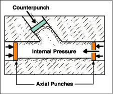 |
| Figure 1: The hydroforming of Y shapes requires an application of a counterpunch to support the protrusion (branch) during forming. |
An increasing number of exhaust components such as T shapes (three-way connectors with a right-angled branch) and Y shapes (three-way connectors with an angled branch) are being hydroformed.
To investigate metal flow in Y-shape hydroforming, the Engineering Research Center for Net Shape Manufacturing (ERC/ NSM) at The Ohio State University conducted several experiments using the tooling available at the SPS Research Center in Aalen, Germany.
A typical tube hydroforming operation involves a controlled application of internal pressure and axial feed of tube material from the tube ends. Hydroforming Y shapes also requires an application of a counterpunch to support the protrusion (branch) during forming (see Figure 1). This allows for forming of the protrusion with a greater length and more uniform thickness distribution.
In this hydroforming operation, the operator places a straight tube blank (see Figure 2a), coated with a solid film lubricant, in the die and seals the ends by the axial punches. The operator then pressurizes the tube blank internally using high-pressure water, while subjecting it to axial compressive stresses from the action of the axial punches. A counterpunch usually provides compressive stresses against the growing protrusion to delay bursting at the protrusion tip, thus increasing the protrusion height (see Figure 2b).
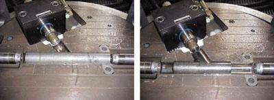 |
| Figure 2a and 2b: To begin Y-shape hydroforming, the operator places a lubricated tube blank in the die (a). The final product is shown in photo b. In these photos, the upper die is removed to show the position of the workpiece. |
To hydroform a Y-shape geometry successfully, a fabricator must select the main process parameters:
Simple metal forming equations or finite element analysis (FEA) simulations can provide initial estimates of the process parameters. Designers then can test and fine-tune these estimates. Ensuring that the initial process parameters are reasonably accurate at the beginning can reduce the number of iterations needed to obtain the best process conditions.
Axial Feeds. The easiest way to estimate the axial feeds needed is to calculate the volume of the tube material at the protrusion section of the Y shape. Assuming that the original tube wall thickness remains unchanged, the designer then can convert the volume of the protrusion to obtain the equivalent axial feed.
The tests at the ERC/NSM were based on a Y-shaped geometry with a fixed angle (see Figure 3). Researchers calculated the volume of material formed into the protrusion area. They assumed that the volume on each half of the protrusion was contributed from the axial feeds. For this particular Y-shaped geometry, the calculated relationship of the axial feeds to the protrusion height (H) indicated that the left and right punches should feed the tube edges 0.8 mm H and 1.3 mm H, respectively. This same procedure can be applied to hydroforming of all Y-shaped geometries.
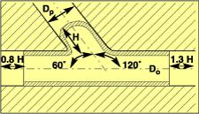 |
| Figure 3: The tests at the ERC/NSM were based on a Y-shape geometry with a fixed angle. The tube blank outside diameter (D0) was 50.5 mm (1.988 inches), initial tube thickness (t0) was 1.5 mm (0.059 in.), and the protrusion diameter (Dp) was 50.5 mm (1.988 in.). |
Initial Tube Length. Once the axial feeds have been estimated, the initial tube length can be calculated by adding the necessary axial feed distances to the final length of the Y shape.
Internal Pressure. Yielding pressure is the minimum pressure required to start tube deformation in the hydroforming process. The analytical model to approximate the yielding pressure is based on a simple axisymmetric bulging of a tube with fixed ends and gives a good initial guess:
| (Pi)y
= sy | 2t0 ______ | ) | Where: | (Pi)y = yielding pressure sy = yield strength of tube material t0 = initial tube thickness D0 = tube diameter |
D0 - t0 |
Bursting pressure is the maximum pressure that can form the tube without bursting and can be estimated as follows:1
| (Pi)b
= su | 4t0 _______ | ) | Where: | (Pi)b = yielding pressure su = ultimate tensile strength | D0 - t0 |
Calibrating pressure is the internal pressure level required to form or coin a tube wall into small die corners and can be estimated by using Equation 3:2
(Pi)max = | 2 | ____ sf | rb | _______ ] | Where: | (Pi)max = calibrating pressure | sf = flow stress of tube material rb = die corner radius t = tube wall thickness 3½ | (rb - t) | |
After determining these three pressure limits, the designer can construct a first initial pressure curve for hydroforming of the corresponding Y shape by using linear lines connecting these pressure limits. The calculated bursting pressure is expected to be larger when a counterpunch is applied. Using iterative FEA simulations, the designer can determine the optimal pressure curve.
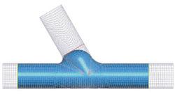 |
| Figure 4: FEA simulation demonstrates intermediate Y-shape hydroforming steps. |
Counterpunch Force. There is no simple formula to determine the appropriate counterpunch force. However, designers can use FEA to estimate the counterpunch force profile. They then can modify the displacement curve governing the counterpunch movement until the desired Y shape can be formed and then determine the counterpunch force from the contact force between the counterpunch and tube protrusion interface.
Researchers conducted FEA simulations to investigate hydroforming of SS 304 Y shapes (see Figure 4), using material properties s = 1.471(0.06+e)0.584 MPa and a friction coefficient of 0.06. The counterpunch's position in the die just above the left die corner radius kept it from pinching the growing protrusion in the early hydroforming stage. After the protrusion came in contact with the counterpunch, the counterpunch would slide up slowly as it supported the growing protrusion and come to a stop during the calibration stage.
FEA simulations estimated and refined the process parameters (internal pressure, axial feeds, and counterpunch force) (see Figure 5), and researchers used these parameters to form the Y shapes in the experiments.
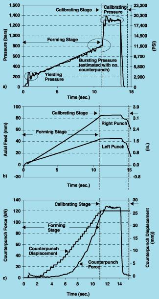 |
| Figure 5 (a-c): The experimental hydroforming of SS 304 Y shapes was based on these curves showing pressure (a), axial feed (b), and counterpunch force (c) versus time curves. |
From Figure 5b, the axial feeds were not applied during the calibrating stage because the calibrating pressure usually was high, making the tube-die interface friction force too large for the tube material to be fed in.
Figure 5c shows the counterpunch force curve and the displacement of the counterpunch, which determines the protrusion height of the Y shape. The Y-shape thickness distributions as calculated by FEA were compared with the corresponding values determined through experiments. The results indicate that FEA predicts metal flow in the Y shapes accurately.
The success of a Y-shape hydroforming operation hinges on the proper selection of many process parameters. To reduce the trial-and-error effort in designing the process parameters, designers can use analytical models to estimate valid process parameter values. Using these values as an initial guess to apply in iterative FEA simulations can help them determine the optimum process parameters.
Suwat Jirathearanat is a graduate research associate and Taylan Altan, Ph.D., is a professor and director of the Engineering Research Center for Net Shape Manufacturing (ERC/NSM), The Ohio State University, 339 Baker Systems, 1971 Neil Ave., Columbus, OH 43210, phone 614-292-5063, fax 614-292-7219, e-mail altan.1@osu.edu, Web site www.ercnsm.org.
Christoph Hartl is general manager of the SPS Research Center, Siempelkamp Pressen Systeme GmbH & Co., ALLFORM Entwicklungszentrum, D-73433, Aalen-Wasseralfingen, Germany, phone +49(0)7361-502-644, fax +49(0)7361-502-639, e-mail ch.hart@sps-pressen.de.
This work was partially supported by the Tube Hydroforming Consortium at the ERC/NSM, The Ohio State University. The authors would like to thank the participating companies and also would like to acknowledge Raimund Stock, SPS Research Center, for his valuable contributions during the experiments.
1. S. Jirathearanat, K. Tibari, and T. Altan, "Evaluation of Metal Flow in Tube Hydroforming Y-shapes," Report No. THF/ERC/NSM-00-R-07 (Columbus, Ohio: The Ohio State University, 2000).
2. M. Koc and T. Altan, "Development of Guidelines for Part, Process and Tooling Design in the Tube Hydroforming (THF) Process: Classification of the Parts and Analytical Models for Prediction of Process Parameters," Report No. THF/ERC/ NSM-98-R-34 (Columbus, Ohio: The Ohio State University, 1998).

The Tube and Pipe Journal became the first magazine dedicated to serving the metal tube and pipe industry in 1990. Today, it remains the only North American publication devoted to this industry, and it has become the most trusted source of information for tube and pipe professionals.
start your free subscription
Easily access valuable industry resources now with full access to the digital edition of The Fabricator.

Easily access valuable industry resources now with full access to the digital edition of The Welder.

Easily access valuable industry resources now with full access to the digital edition of The Tube and Pipe Journal.

Easily access valuable industry resources now with full access to the digital edition of The Fabricator en Español.
In this episode of The Fabricator Podcast, Caleb Chamberlain, co-founder and CEO of OSH Cut, discusses his company’s...


