


Contributing Writer
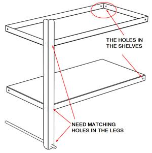
: Figure 1: The leg needs holes for bolts and the axle.
Part VII of this series of articles ended with a promise to demonstrate a few techniques for adding holes in the legs to match the shelves. We are going to continue our theme of locating features in the context of our top-level assembly. A few of the components of immediate concern are shown in Figure 1.
(The usual disclaimer: If you’re not using the same 3-D CAD software as I am, then you’ll have to translate some of the terminology. However, the concept of parametric modeling is widely applicable.)
The leg part in Figure 1 has no holes. We want to add holes for bolts to attach the shelves. We also need a hole for the axle. One of our design goals is to make this shelf easy to assemble. Fewer unique parts might help with that. So the plan is to use the same leg in all four corners.
This plan produces a symmetric part, which goof-proofs the manufacturing a bit. However, it has the drawback of some unused holes in the final assembly. We’ll see that more clearly in the next installment of this article.
The axle hole is a different diameter from the bolt holes, so let’s create a separate feature for the axle hole and another for the bolt holes. It doesn’t really matter which hole we do first. Let’s cut an axle hole first. In the future, if the design should change the size or location of the axle, we want this hole to update automatically.
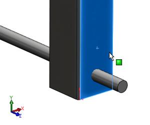
With the assembly open, Edit the leg part. Then launch the Extruded Cut tool. Cuts made with the Extruded Cut tool need two things: a starting plane and a sketch. Select a face on the leg that the axle passes through, as shown in Figure 2a. That will be the starting plane, also known as the Sketch Plane. We’re now editing a sketch that will become the hole for the axle.
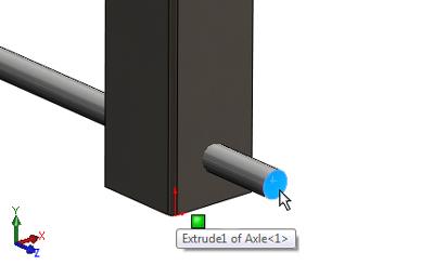
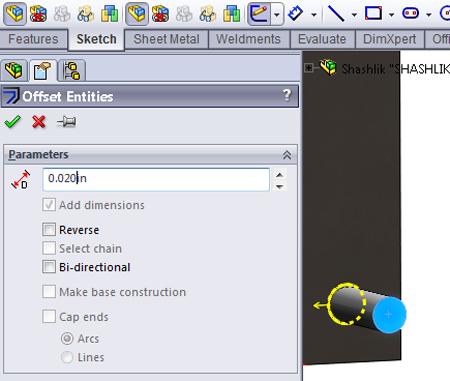
In Figure 2b we’ve selected the face on the end of the axle. Use the Offset Entities tool to create a circle that is larger than the axle shaft—0.020 inch should do the trick. The PropertyManager dialogue for this is shown in Figure 2c.
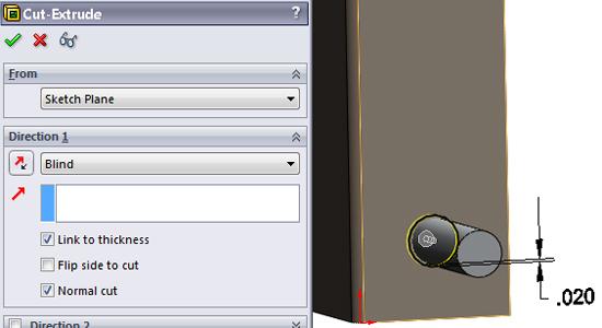
Upon exiting the sketch, the PropertyManager dialogue for the Extruded Cut will appear as shown in Figure 2d. We want to use two handy settings. The first is Link to Thickness. This guarantees that the hole always will match the material thickness, which is a blessing if we should change the gauge of the leg in the future. The second setting is Normal Cut. If I had written the software, I would have called it Punched Cut because a Normal Cut is exactly like a punched hole—perpendicular to the sheet metal.
A design might call for a hole to be drilled at an angle to the face of the sheet metal. If that’s what you’re trying to do, then deselect the Normal Cut option.
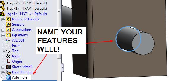
When you’re ready, click on the green check mark to dismiss the Cut-Extrude PropertyManager. The system will create the extruded cut. You should see the air gap between the leg and the axle. This is a good time to rename the Cut-Extrude feature you just created. In Figure 2e you can see that I’ve renamed it “Axle Hole.” Although this renaming of features isn’t absolutely necessary, it is generally helpful during design reviews and in the future when the design will be revised.
Speaking of air gaps, you know that in reality the leg will rest against the axle. The perfect air gap that we’ve modeled will exist only in the CAD system. Instead of an offset circle, we could have sketched and dimensioned a circle and made it tangent to the axle. That would result in a more realistic model. I’ll leave it to you to decide how elaborate you want your model to be.
We want this leg to work in any of the four corners of the grill, so we need to duplicate the axle hole on the other side of the leg. One way to do that is to use the Mirror tool, which needs two things—a reference plane and one or more features to be mirrored.
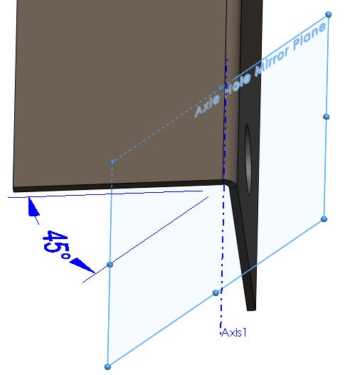
Our reference plane needs to bisect the leg. Depending on the software you’re using, you could create a Mid-Plane that resides halfway between the two faces of the leg, as shown in Figure 3. Older versions of the software require creating an axis at the center of the bend radius and then creating a plane through that axis at a 45-degree angle, as shown in Figure 4.
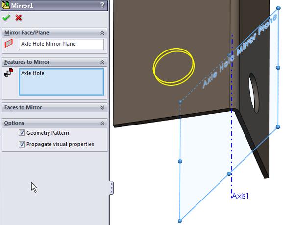
Once you have the reference plane created, mirroring the axle hole to the other side of the leg is a snap. Figure 5 shows the PropertyManager dialogue. The Geometry Pattern option helps the CPU out a little by minimizing the amount of calculation needed. Because this leg has very simple features, this option works just fine.
In Part IX of this series, we’ll finish up the legs and get started on the charcoal pan and vents.
Keep in mind that this top-down modeling technique we’re using is not the only way to do this work. It may not even be the best way in every situation. However, when it comes to virtual prototyping, it is efficient to use parametrically driven features. It takes some time to set up initially, but it will pay off later by speeding the revision process. The use of reference geometry to control parametric features reduces the complexity of figuring out what drives what.
Gerald would love to have you send him your comments and questions. You are not alone, and the problems you face often are shared by others. Share the grief, and perhaps we will all share in the joy of finding answers. Please send your questions and comments to dand@thefabricator.com.


The Fabricator is North America's leading magazine for the metal forming and fabricating industry. The magazine delivers the news, technical articles, and case histories that enable fabricators to do their jobs more efficiently. The Fabricator has served the industry since 1970.
start your free subscription
Easily access valuable industry resources now with full access to the digital edition of The Fabricator.

Easily access valuable industry resources now with full access to the digital edition of The Welder.

Easily access valuable industry resources now with full access to the digital edition of The Tube and Pipe Journal.

Easily access valuable industry resources now with full access to the digital edition of The Fabricator en Español.
In this episode of The Fabricator Podcast, Caleb Chamberlain, co-founder and CEO of OSH Cut, discusses his company’s...


