


Contributing Writer
Hydroforming machines--whether designed for sheet or tubular hydroforming--rely on fluid to form or shape metal blanks into finished or semifinished components. While designing a machine for tubular hydroforming can be a monumental task, designing one for sheet hydroforming is more complex because of the larger active areas and resulting high forces needed to form metal sheet.
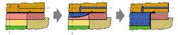 |
| Figure 1: The new press was designed for fluid-based forming of sheet metal. Source: Kleiner, Homberg, and Brosius,"Processes and Control of Sheet Metal Hydroforming." |
A new type of hydroforming press recently was developed for sheet applications. Supported by the Deutsche Forschungsgemeinschaft (DFG, or German Research Society, www. dfg.de), the press was developed jointly under the direction of Prof. Dr.-Ing. M. Kleiner of the University of Dortmund (www.uni-dortmund.de) and Siempelkamp Pressen Systeme (www.sps-pressen.de).
The process sequence for sheet hydroforming, for which this machine specifically was designed, is shown in Figure 1. In addition to performing hydroforming, the press incorporates data acquisition and control features necessary for research.
Process requirements are important parameters, or boundary conditions, of any machine design. The potential for using sheet hydroforming presses to manufacture large-surface sheet metal components from steel, high-tensile steel, and nonferrous materials is substantial. One example is external vehicle outer body panels. Other possible applications include technologically ambitious designs and components with complex contours, such as automobile fuel tanks.
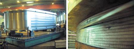 |
| Figure 2: The press achieves a clamping force of 11,300 U.S. tons (100 MN), which is absorbed by a single cast frame with a circumferential pretensioning system. Left: machined frame Right: spring steel wire winding |
Because this press is used for research, design, and sample process development, cycle time is not crucial. However, the machine can handle large-scale production applications.
Rough estimates show that the clamping forces required to hydroform outer body parts such as roofs, trunk lids, and engine hoods are 56,000 to 68,000 U.S. tons (500 to 600 meganewtons). Current press frame designs, which include conventional tube hydroforming and sheet forming equipment, are not economical for large presses because of the longer cycle times per part.
One of the goals in designing this new press was to find an economical design for high clamping forces.
The press (see Figure 2) achieves a clamping force of 11,300 U.S. tons (100 MN), which is absorbed by a single cast frame with a circumferential pretensioning system. The machined frame is made of SG cast iron and measures 22 by 9.6 by 5.6 feet (6.6 by 2.9 by 1.7 meters) and weighs 94.8 U.S. tons (86 metric tons).
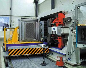 |
| Figure 3: For process reasons, the frame is arranged horizontally, which results in improved fluid handling because the workpiece still may contain up to 100 liters of water at the end of the process. |
The pretensioning system consists of 25 layers, each with 160 spring steel wire windings that weigh 8.8 U.S. tons (8 metric tons). The weight of the complete wire-wound frame is 103.6 U.S. tons (94 metric tons). The result is a compact but lightweight design with a high clamping force capability.
The wire-wound system puts the frame into a prestressed compressive condition so stresses induced during the complete press cycle are within this compressive stress range. The maximum stress exerted on the press frame thus is considerably lower than a frame without prestress because the high initial compressive stress can support large stress amplitudes.
Conventional sheet hydroform press arrangements with horizontal dies can lead to process handling difficulties and workpiece deformation because of the volume of fluid (up to 100 liters) remaining in the part after forming. This press frame is arranged horizontally (see Figure 3) with vertical dies to improve fluid handling and reduce part deformation.
The press can be equipped with a die shuttle system so that during the forming process the die can be loaded and unloaded outside the press, which reduces the cycle time. The horizontal arrangement also enables the use of multiple die cassettes. This capability decreases individual part cycle time because multiple dies result in increased productivity.
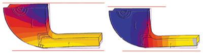 |
| Figure 4: The press's frame has to withstand deflection under load, as well as the net weight of the main cylinder. Horizontal frame deflection is 5.4-mm expansion; vertical frame deflection is 6.3-mm contraction. |
Because the frame has a horizontal arrangement and a pretensioning system, additional boundary conditions, such as the weight effect of the main ram, must be taken into consideration. The press design has to withstand frame deflection under load (see Figure 4), as well as the net weight of the main cylinder.
Conventional ram guiding at the frame is not possible because of the sizable frame contraction that occurs during loading. The ram is guided vertically by the machine base and horizontally by lateral guides situated in the frame's neutral deflection region (see Figure 5).
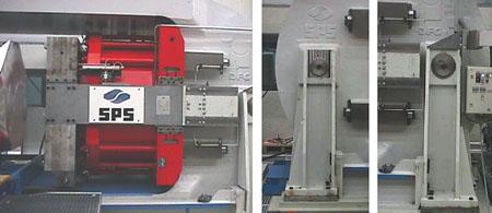 |
| Figure 5: The ram is guided vertically by the machine base and horizontally by lateral guides situated in the frame neutral deflection region. Left: ram guiding Middle: movable bearing Right: fixed bearing |
To allow for deflections under load, the frame is supported at the machine base by a fixed bearing (on the closing cylinder side) and a movable bearing (on the die side) (see Figure 5).
A push-pull die change unit is incorporated to accommodate dies up to 5.4 by 5.4 by 2.6 ft. (1.65 by 1.65 by 0.8 m) and a maximum allowable die weight of 16.5 U.S. tons (15,000 kg). The dies are prevented from overturning during die change (see Figure 6).
The press's closing force of 11,200 U.S. tons (100 MN) is generated by a horizontally mounted cylinder with an operating pressure of 10,150 pounds per square inch (PSI) (700 bar). This operating pressure gives optimum cylinder size and deflection under load. The process requirements dictate that the ram movement and blank holder functions are separated.
A single drive unit drives the total forming system with a capacity of 177 HP (132 kW) with a main pump flow of 53 gallons per minute (GPM) (200 liters per minute).
Before it can be formed, the part must be filled by a prefill pump that develops 43 to 73 PSI (3 to 5 bar) and a flow of approximately 26 GPM (100 l/min.). The process continues by further pressurizing the part up to 4,300 PSI (300 bar) with a prefill cylinder with a volume up to 26.5 gal. (100 l) at an adjustable volume flow rate up to 14 GPM (52 l/min.). This enables the forming speed to be controlled over a wide range.
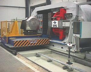 |
| Figure 6: A push-pull die change unit is incorporated to accommodate dies up to 5.4 by 5.4 by 2.6 ft. (1.65 by 1.65 by 0.8 m) and a maximum allowable die weight of 16.5 U.S. tons (15,000 kg). |
Next the process switches to a pressure intensifier that supplies fluid up to 29,000 PSI (2,000 bar) and a volume of 1.3 gal. (4.8 l) to calibrate the component. A special control function allows reloading of the intensifier during the forming process for particular process and die requirements.
The blank holder on the die side can be pressure- or force-regulated by individual membrane cylinders to meet process requirements. Up to 10 individual membrane cylinders or cylinder circuits can be activated individually (10 valves). Blank material infeed can be detected by plate infeed sensors.
 |
| Figure 7: The total hydraulic control module is compact, which can aid in quick setup and commissioning. |
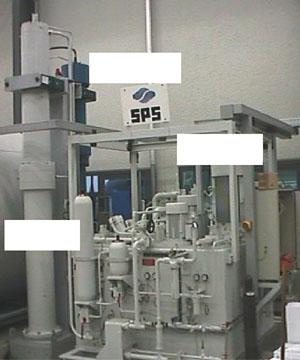
At the ram side in the die, additional ejector or loading support functions can be activated. A vacuum initially holds and positions blanks or plates in the die. All described axes can be operated in parallel, which replicates the theoretical forming process. The total hydraulic control module is compact, which can aid in quick setup and commissioning (see Figure 7).
Because this unit is used for prototyping only, a compact band filter system with an oil skimmer is installed for filtering the forming medium (see Figure 8). A cooling unit is unnecessary because long intervals between operating cycles preclude heat buildup. However, a cooling unit could be installed if required. The hydraulic and control systems also were designed to allow axial forming cylinders for tubular hydroforming.
This machine was designed for research, and the controls were designed for flexibility and future upgrading. All set values and resulting actual values can be systematically recorded for full process documentation.
During the forming process, all data--set and actual values--are graphically displayed and can be observed and recorded. All data also may be displayed and analyzed using conventional office software independently of internal graphic analysis. Data analysis and press operation, such as continuous operation for production simulation, can be performed simultaneously.
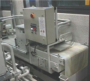 |
| Figure 8: Because the unit is used for prototyping only, a compact band system with an oil skimmer is installed for filtering the forming medium. |
All machine and process data can be stored and analyzed offline via an Ethernet connection. The machine also is equipped with a modem for direct, secure Internet access. Remote access to a press for maintenance checks and analysis is achieved via modem or ISDN terminal adaptor.
The machine control is based on a Siemens-S7-400 programmable logic controller with a 415-2DP central processing unit with operator interface visualization running on a PC. User guidance is graphically interactive with the operator control via a keyboard, mouse, or trackball. The user interface was designed specifically for hydroforming applications.
Markus Erras is a managing director with hydroforming pioneer Siempelkamp Pressen Systeme GmbH & Co., Mevissenstraße 65, D-47803 Krefeld, Germany, phone +49 2151 895-5, fax +49 2151 895-998, e-mail allform@sps-pressen.de, Web site www.sps-pressen.de. Siempelkamp Pressen Systeme manufactures hydroforming presses and hydraulic presses for various metal forming applications.
The author thanks the following colleagues for their help in the preparation of this article: A. Böhm, D. Elsinghorst, R. Ludwig, and T. Abbey.
M. Kleiner, W. Homberg, and A. Brosius, "Processes and Control of Sheet Metal Hydroforming," in proceedings from the 6th ICTP, Nürnberg, Sept. 19-24, 1999, pp.1243-1252.
N.N.: "Colloquium Sheet-Metal Hydroforming," Dec. 11, 2001, within the DGF program, "Media-based Production Methods for Plate Forming," University of Dortmund, conference paper.
M. Kleiner, W. Homberg, E.-P. Warnke, and W. Voß, "Linked Casting Frame for 100-MN Hydroform Presses," special print of Siempelkamp Designing and Building, presented at EMO- Fair 2001, Hannover, Germany.

The Tube and Pipe Journal became the first magazine dedicated to serving the metal tube and pipe industry in 1990. Today, it remains the only North American publication devoted to this industry, and it has become the most trusted source of information for tube and pipe professionals.
start your free subscription
Easily access valuable industry resources now with full access to the digital edition of The Fabricator.

Easily access valuable industry resources now with full access to the digital edition of The Welder.

Easily access valuable industry resources now with full access to the digital edition of The Tube and Pipe Journal.

Easily access valuable industry resources now with full access to the digital edition of The Fabricator en Español.
In this episode of The Fabricator Podcast, Caleb Chamberlain, co-founder and CEO of OSH Cut, discusses his company’s...


