Contributing Writer
- FMA
- The Fabricator
- FABTECH
- Canadian Metalworking
Categories
- Additive Manufacturing
- Aluminum Welding
- Arc Welding
- Assembly and Joining
- Automation and Robotics
- Bending and Forming
- Consumables
- Cutting and Weld Prep
- Electric Vehicles
- En Español
- Finishing
- Hydroforming
- Laser Cutting
- Laser Welding
- Machining
- Manufacturing Software
- Materials Handling
- Metals/Materials
- Oxyfuel Cutting
- Plasma Cutting
- Power Tools
- Punching and Other Holemaking
- Roll Forming
- Safety
- Sawing
- Shearing
- Shop Management
- Testing and Measuring
- Tube and Pipe Fabrication
- Tube and Pipe Production
- Waterjet Cutting
Industry Directory
Webcasts
Podcasts
FAB 40
Advertise
Subscribe
Account Login
Search
The basic elements of tubular hydroforming
- By Mustafa Ahmetoglu
- March 5, 2001
- Article
- Hydroforming
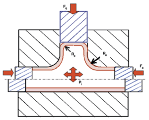
Figure 1Modern hydroforming machines have independent control of axial feeding, internal pressure, and counterpressure.
Tube hydroforming has been well-known since the 1950s. However, with recent advancements in computer controls and high-pressure hydraulic systems, the process has become a viable method for mass production, especially with the use of internal pressures of up to 6,000 pounds per square inch (PSI).
Modern machines have independent control of axial feeding, internal pressure, and counterpressure (see Figure 1), which increases the material-shaping capability of the process tremendously over other, more traditional forming methods.
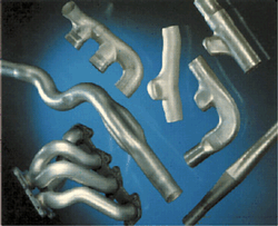
Numerous applications of hydroforming can be seen in exhaust manifolds (see Figure 2) made of stainless steel tubes. The BMW 5 series features a hydroformed aluminum rear axle. Seam welded tubes from 5000 series aluminum alloys were selected for this product because of the complications and distortions that resulted from annealing of 6000 series alloys.
In addition, Volvo Car Corp. has selected the front end of the Volvo 850 to conduct a research and development project with hydroform-intensive aluminum-based frame construction. Volvo has reported 50 percent less weight, 45 percent fewer parts, 45 percent fewer weld seams, and tighter tolerances compared to its conventional body-in-white designs.
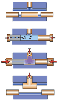
The process sequence for a typical hydroforming operation follows the progression illustrated in Figure 3. Fluid pressure within the tube is increased after the die closes to force the material into the deformation zone. During this process, axial feeding and internal pressure are controlled simultaneously to improve the process's material-shaping capabilities.
When hydroforming extruded aluminum profiles, stretching a tube's cross section beyond its yield point (2 to 3 percent elongation) is required to prevent springback and achieve tight tolerances. Having flanges and webs in the extruded tube makes the die geometry and sealing more complicated. In many cases, a large amount of axial feeding is not possible.
Advantages and Disadvantages of Hydroforming
Tube hydroforming allows engineers to optimize their designs through cross sectional reshaping and perimeter expansion. Combined with the ability to inexpensively create the holes that are required for vehicle subsystem interfaces, hydroforming has become a critical technology for structural components in mass-produced vehicles.
Hydroforming tubular components offers several advantages, including:
- Part consolidation.
- Weight reduction through more efficient section design and tailoring of the wall thickness.
- Improved structural strength and stiffness.
- Lower tooling cost as a result of fewer parts.
- Fewer secondary operations.
- Tight dimensional tolerances and low springback.
- Reduced scrap.
Hydroforming also has some drawbacks, including:
- Slow cycle time.
- Expensive equipment.
- Lack of extensive knowledge base for process and tool design.
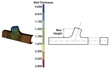
Therefore, the feasibility of hydroforming has to be investigated from both an economic and mechanical standpoint for each individual part. To reduce cycle times, secondary operations, such as piercing, need to be integrated with the hydroforming process. Computer simulation of the hydroforming process also can and should be used to evaluate the limits of deformation (see Figure 4).
Factors Affecting the Tube Hydroforming Process
As hydroforming becomes more widely used, several issues must be addressed to increase the implementation of this technology in the stamping industry. These issues include:
- Preparation of tubes, which involves material selection and quality of the incoming tube.
- Preform design and production method.
- Part design for hydroforming.
- Welding and assembly of hydroformed components - - that is, fixturing and joining.
- Crush performance and joint stiffness.
- Selection of a lubricant that does not break down at high pressures.
- Rapid process development.
Tube Material and Formability
Several factors play an important role in selecting material for tube hydroforming, including final properties of the part, forming process and deformation capabilities, availability, and cost. In many cases, material selection may entail a trade-off between cost and structural performance. Tubes from low-carbon steel (1010, 1008) and aluminum alloys (5019-O, 5754-O, 6060-T4, 6063-T4, 6082-T4) typically are used in body and chassis applications. Stainless steel (304, 309) tubes are generally used in exhaust applications.
The quality of the incoming tube is critical for the success of the hydroforming process. Material properties - such as material composition, yield strength, ultimate tensile strength, percent elongation - and flow characteristics and dimensions of the tube must be determined based on the final part requirements. These properties also must be monitored closely during the manufacturing process.
Accurate material data also is required for the part and process development. Formability limits (see Figure 5) determined in laboratory tests can be used efficiently in computer simulations to identify problem areas in hydroforming and correct them before starting expensive and time-consuming process development.
Friction
The main parameters that affect friction in tube hydroforming are the lubricant; the tube material properties, such as surface texture and yield strength; and the die surface, which involves surface finish, hardness, surface treatment, and coating.
Selecting the proper lubricant depends on the internal pressure and the sliding velocity and distance involved for a particular part. Various types of lubricants are available for hydroforming. These include solid lubricants, which are mostly graphite-, MoS2-, or polymer-based; waxes; oils; and emulsions. Operators should be able to apply and remove the lubricant easily during the operation. In addition, the lubricant should not contain any polluting elements.
Tube Bending and Preforming
The starting tube geometry for hydroforming may be straight or it may have a prebent or preformed shape, depending on the complexity of the final product. In many applications, tube is prebent to the approximate contours of the final part before the hydroforming operation begins. Parts that require excessively tight bends; have short, straight sections between the bends; or require multiple bend radii may incur higher tool and equipment costs. Therefore, limits of the bending operation should be taken into consideration during the product design stage.
Because of material hardening during the bending and preforming of the tube before it is hydroformed, material properties change, and some of the tube's formability is already used up. Therefore, to achieve large expansions during hydroforming, either an intermediate annealing step is required, or a material with high ductility should be selected.
However, because the ductility of aluminum alloys is limited when compared to steel's, most hydroformed parts made with aluminum alloys are limited to calibration to achieve tight dimensional tolerances after bending.
Equipment
The main functions of a hydroforming press are to open and close the die, provide clamping load during the forming process to eliminate elastic deflections, and die separation. Additional units that are required to carry out the process include axial force cylinders and a pressure intensifier.
Currently, hydraulic presses are used to provide large clamping forces during the process. These presses are usually very expensive. However, several low-cost equipment designs with separate actions for opening/closing the tooling and providing the clamping load are being developed by press companies.
The number of tube hydroforming applications will increase by better understanding of materials and the process. In many cases, reliable computer simulations will help in developing more robust hydroforming techniques.
Selection of proper materials and lubricants is critical for the success of the process. Advanced materials and lubricants are being developed in various research institutes and companies.
About the Author
Mustafa Ahmetoglu
1181 Trapp Road
St. Paul, MN 55121
651-905-4888
subscribe now

The Fabricator is North America's leading magazine for the metal forming and fabricating industry. The magazine delivers the news, technical articles, and case histories that enable fabricators to do their jobs more efficiently. The Fabricator has served the industry since 1970.
start your free subscription- Stay connected from anywhere

Easily access valuable industry resources now with full access to the digital edition of The Fabricator.

Easily access valuable industry resources now with full access to the digital edition of The Welder.

Easily access valuable industry resources now with full access to the digital edition of The Tube and Pipe Journal.
- Podcasting
- Podcast:
- The Fabricator Podcast
- Published:
- 04/16/2024
- Running Time:
- 63:29
In this episode of The Fabricator Podcast, Caleb Chamberlain, co-founder and CEO of OSH Cut, discusses his company’s...
- Trending Articles
Tips for creating sheet metal tubes with perforations

Supporting the metal fabricating industry through FMA

JM Steel triples capacity for solar energy projects at Pennsylvania facility

Are two heads better than one in fiber laser cutting?

Fabricating favorite childhood memories

- Industry Events
16th Annual Safety Conference
- April 30 - May 1, 2024
- Elgin,
Pipe and Tube Conference
- May 21 - 22, 2024
- Omaha, NE
World-Class Roll Forming Workshop
- June 5 - 6, 2024
- Louisville, KY
Advanced Laser Application Workshop
- June 25 - 27, 2024
- Novi, MI


