


Contributing Writer
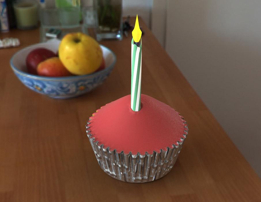
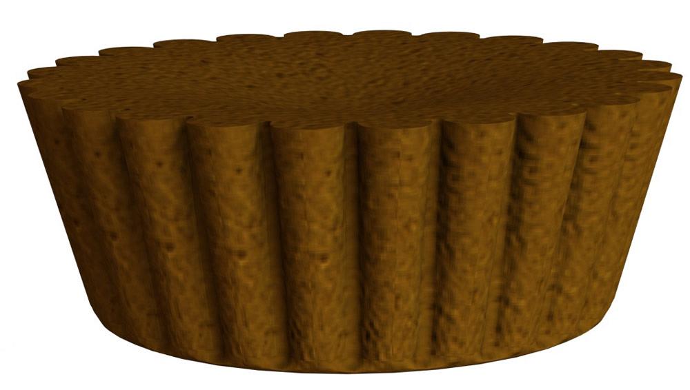
Figure 1a
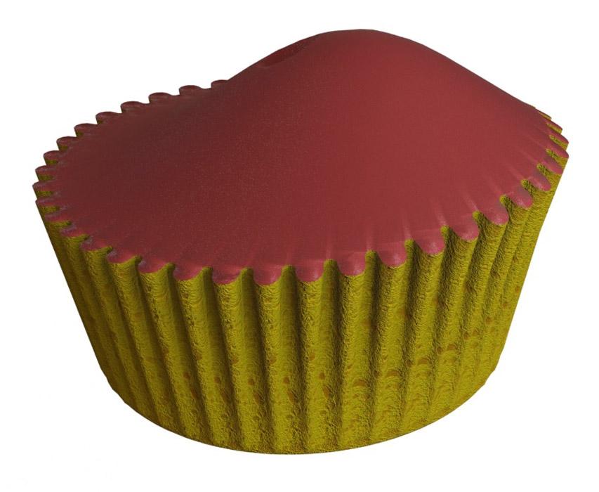
An assembly of a foil baking cup, cake with icing, and a candle is shown. A different configuration of this assembly was used to make Figure 1b.
Figure 1a and 1b are examples of CAD models that might be useful as accessories when presenting or demonstrating a design. These sorts of “bling” models are not intended for fabrication. Rather, they serve as visual references in a scene.
The Figure 1a cupcake model features a pleated baking cup, sponge cake under pink icing, and an LED wax candle. The coffee filter and grounds in Figure 1b are dimensionally correct but unnaturally perfect—no wrinkles in the paper and the grounds are like sand.
While these models are lacking in some fidelity, they could be refined to be visually appetizing if that were needed. The cute CAD trick demonstrated here is a single CAD assembly configured to switch to be either a cupcake or filtered coffee grounds.
Our tour through the modeling techniques used will include some surface modeling, the use of equations, configurations, a design table, and the use of deform and dome features to get swoopy without really trying.
The assembly of paper cup, cup stuffing, and candle is configured to select which configuration of the pleated cup is in use at any time; that is, either 24 pleats in a coffee filter-sized basket or 42 pleats in a cupcake liner. The assembly does the same selection for the cup stuffing—sponge or sand. Yum.
This example of configuration-driven modeling is a bit contrived; how often does one need to quickly switch between coffee and cupcake? In practical terms, a configured model makes sense for something that comes in different sizes. Consider a model of the pleated cup. During the design stage, the optimum selection of pleats and volume may evolve. Configured models of pleated cups allow for easy drop-down selection of their size in the assembly being designed.
For switching between cupcakes and coffee, the configuration management is more complex. Not only are the quantity and size of pleats changing in the paper cup, but appearances change between cake and coffee, paper and foil, and the candle comes and goes.
CAD tip: Use configured assemblies to show variations in product lines where many items are in common; otherwise, use discrete assemblies for each product line. Use configured components for drop-down selection in an assembly. Configured components are great for items that are purchased as opposed to manufactured per custom specification.
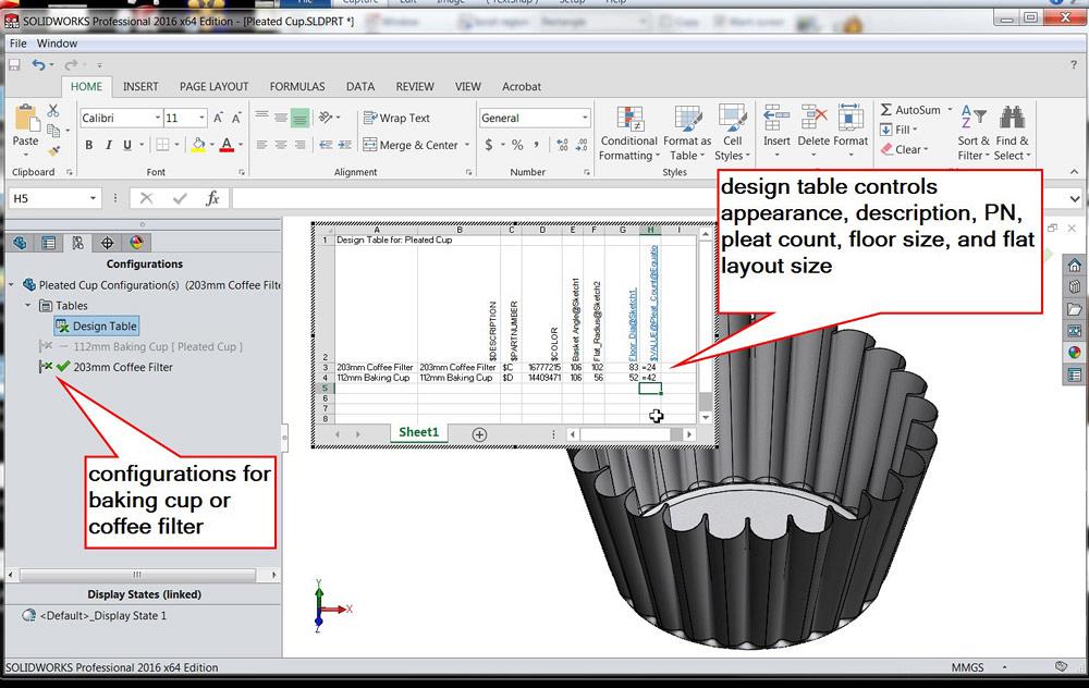
The pleated paper cup model is shown in Figure 2a. It uses global variables, equations, and a couple of configurations to control pleat count, floor diameter, wall angle, and flat size. Figure 2b shows its design table. This is where the number of pleats and the size of the paper cup are set.
The assembly of candle, cake, and cup has two configurations, but unlike the pleated cup part, it does not have a design table. This decision was made largely because only a few details change between the assembly’s two configurations—specifically, the type of pleated cup and the type of cup stuffing. And the candle looks strange in coffee, so the assembly’s configuration must make it appear or disappear.
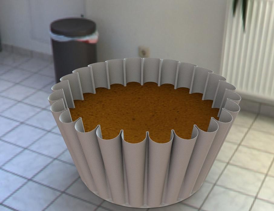
Figure 1b
An assembly of paper coffee filter and coffee grounds is shown. This same assembly was used to make Figure 1a.
When more than a few things change between configurations—for example, thread size, chamfers, length, head size, and shank length—the design table becomes extremely useful. It is simply an embedded spreadsheet. The table format makes it easier to edit the matrix of settings for each configuration.
The pleated cup model uses equations and global variables to calculate the length and shape of the pleats. Based on the flat paper disk size, the cup’s floor size, and the number of pleats, these equations derive the values for dimensions driving sketches in the model.
A sneaky trick used was a second sketch of part of the flat layout. This sketch features driven dimensions that inform the rest of the model exactly what the pleat’s flat widths are, both at its top and bottom.
As a modeling technique, 3-D solid bodies allow for intuitive planning and speedy results. Surface modeling tools are handy for shapes that don’t have many linear edges or flat faces, like a pleated paper cup. Planes and sketches are invaluable to surface modeling.
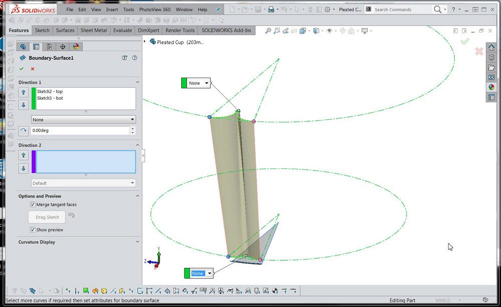
A modeling solution for the paper cup is hinted at in Figure 2c. A wedge of the floor appears in gray. This rotated floor surface was created in preparation for Figure 2c. While in Figure 2c, a boundary surface is being defined from a pair of sketches for the pleat’s top and bottom.
In each pleat sketch, the length of the arcs of the paper folds are dimensioned. With the dimension tool, click on the end of the arc, on the arc, and on the other end of the arc. The value of that arc length dimension is then linked to a global variable.
Recall that those target arc lengths are calculated and made available as global variables by a sketch based on the number of pleats, the size of the flat paper disk, and the manually specified value for the inner crease radius.
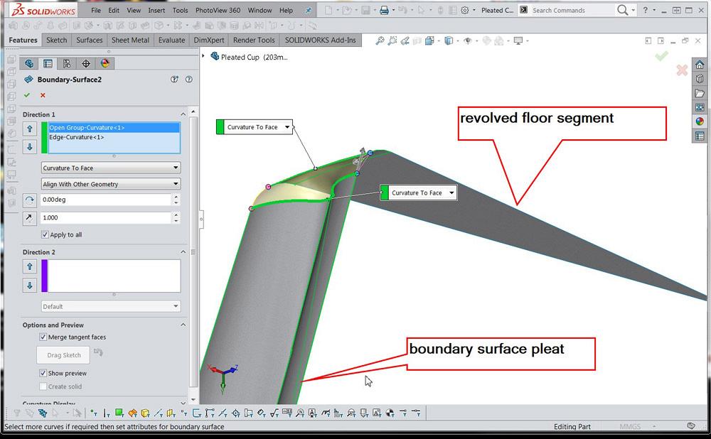
After the pleat crease surface is created, another boundary surface is created to connect the floor segment to the pleated wall (see Figure 2d). The Boundary Surface tool is awe-inspiring in its range of application. It’s a software marvel.
The top rim of the actual basket is scalloped due to the way the paper folds. A surface was rotated to represent that limit of the basket’s rim. To see this, you’ll need to download the CAD model, which is available at www.thefabricator.com/author/gerald-davis. That surface is used as a trimming tool to clip the pleat to the right length. The trimming surface is then hidden and forgotten about.
The three surfaces for floor, bend, and pleat are then used in a circular pattern to create the entire outer surface of the basket. The circular pattern count is a designer’s decision and is controlled with a global variable that is set in a design table so that each configuration of the model has the correct pleat count.
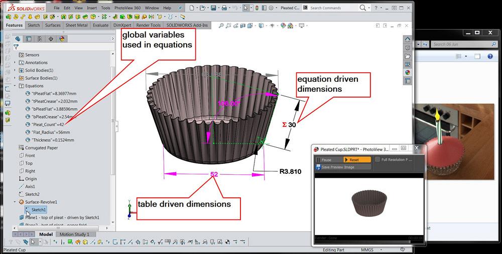
Figure 2a
The pleated cup model uses global variables, equations, and driven dimensions. The flat size of the paper, the diameter of the floor, and the wall angle drive the size of the pleats and the depth of the basket.
The circular pattern of surfaces is then knitted to make a single surface. That surface is then thickened to create a conventional 3-D solid model. As a disclaimer, this is one of many possible solutions to modeling a pleated paper cup.
Figures 3a and 3b show the two configurations of the cup stuffing. In Figure 3a, the appearance of the icing—soft-touch red plastic—is obtained with the Photoview option to radius edges during rendering. The cup stuffing model also uses a design table to control the appearance and depth of the stuffing. The cavity tool uses the pleated cup to trim the stuffing body so it matches the paper cup’s interior.
This cavity feature is updated in the assembly during rebuild and takes CPU time in bunches. It’s labor-saving for the CAD jockey, but tough on the computer. It might be wise to “freeze” this stuffing model once the assembly design is acceptable. As quick-trick modeling tools, dome and deform were used to poke a pocket for the candle, make the cake rise, or make the coffee grounds sink. These features are turned on/off by the stuffing’s design table.
To create such models, we could break the modeling task into patterns, use surfacing tools where appropriate, and embrace design tables. Use equations—and detached sketches purely for calculation—prudently because they only make sense while you’re creating them.
Gerald would love to have you send him your comments and questions. You are not alone, and the problems you face often are shared by others. Share the grief, and perhaps we will all share in the joy of finding answers. Please send your questions and comments to dand@thefabricator.com.


The Fabricator is North America's leading magazine for the metal forming and fabricating industry. The magazine delivers the news, technical articles, and case histories that enable fabricators to do their jobs more efficiently. The Fabricator has served the industry since 1970.
start your free subscription
Easily access valuable industry resources now with full access to the digital edition of The Fabricator.

Easily access valuable industry resources now with full access to the digital edition of The Welder.

Easily access valuable industry resources now with full access to the digital edition of The Tube and Pipe Journal.

Easily access valuable industry resources now with full access to the digital edition of The Fabricator en Español.
In this episode of The Fabricator Podcast, Caleb Chamberlain, co-founder and CEO of OSH Cut, discusses his company’s...


