


Contributing Writer
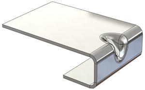
Figure 2: This sheet metal part has a stiffening gusset in the bend.
Fabricators are helpful lots, making it their mission to help customers improve their design’s fit with available manufacturing processes.
When my father started his shop in the late 1960s, part of what captured his customers’ allegiance was his willingness to explain the constraints of fabrication machinery in terms that draftsmen could appreciate and implement. In some cases, he used a drafting board on vellum with a Rotolite® ammonia print duplicator to make copies of drawings of parts that he designed on behalf of hiscustomers.
When I donned the hat of technology officer for the firm in the 1990s, I quickly tired of the drafting board. We upgraded our helpfulness to include 2-D CAD drafting services and later 3-D CAD.
As a matter of full disclosure, in 2004 we separated our design service from our fabrication business. It was clear that we had trained our fabrication customers to expect free drafting services from us. They balked at our invoicing them for CNC programming, let alone computer-aided design and drafting. When we insisted that the CAD work be billed separately from any manufacturing work, wefound that their objections to billing largely vanished. That may have been because of their internal accounting process for research and development as opposed to straight production costs.
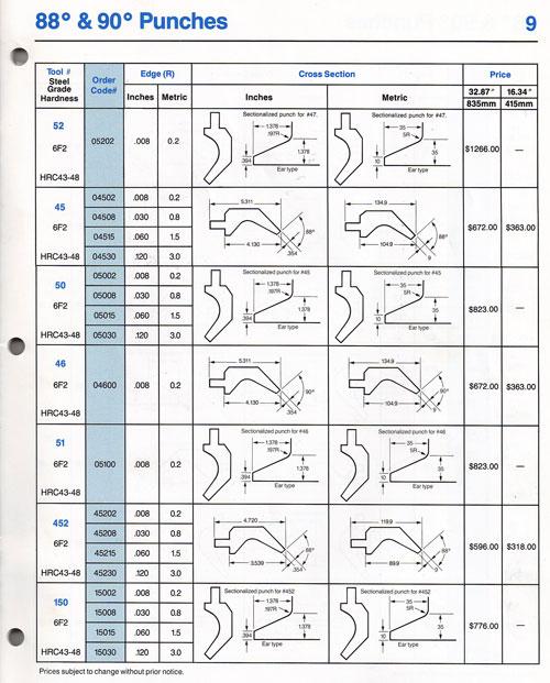
Our first CNC system was a paper-tape punch driven by a DEC PDP-8 computer, eventually replaced by an HP vectorscope and thermal printer. The history of computer-aided drafting (some think CAD is an acronym for computer-aided design) in our shop started with the next of our CNC programming systems to run on a PC. We tried the new 2-D CAD software out on an in-house tooling design project.Figure 1 This a page from a catalog for press brake tooling that was published by Amada Engineering and Service Co. Inc. in March 1991. It’s good stuff, but weneeded to fabricate the part shown in Figure 2. Custom spacer plates are required to form the stiffener gusset in the bend. The catalog page for the tooling didn’t have enough detail for our purposes.
Figure 3 shows a screen shot that looks a lot like AutoCAD® R2.5 running on a Tandy 2000. The 2-D CAD system was “built-in” with the CNC programming package that we purchased. The CNC side ran as an add-in to AutoCAD. It was immediately useful to be able to edit the profile of the spacer to match both the tooling and the specific project at hand.
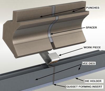
Figure 4 shows the basic components of the setup at the press brake. A rectangular plate—the gusset-forming insert—separates a pair ofstock V dies in the bed of the brake. In this example, the plate is 0.25 in. thick—twice the 0.125-in. inside radius of the gusset. I’ve added a radius to the working edge of the insert to avoid marring the workpiece because it is aluminum. Depending on the ductility of the workpiece and the size of the gusset, you may not need to do that in practice.
The upper punches are spaced to force the workpiece to flow around the gusset-forming insert. From some R&D and a sign-off from the customer, we learned that the spacing needed to be pretty close to 0.700 in.—thus our need for the spacer up top to ensure that the same setup was made for each batch of parts.
Illustrations like Figure 4 are a good way to document press brake setups. Back in the day, we documented this setup with a pencil sketch on a cart top and a lot of waving of the arms and hands. By seeing this CAD model—as an eDrawing perhaps—and having access to a workstation, the press brake operators can spin the model in 3-D space to better see details of the setup.
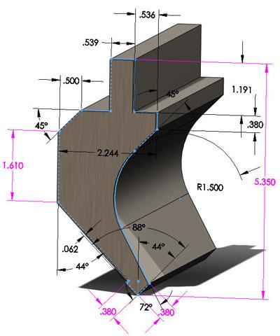
Let’s consider how much went into creating Figure 4 and then evaluate the return on investment. Figure 5 shows that a2-D sketch of the tool profile is extruded to create a 3-D part. Note the similarity between Figure 3 and Figure 5, that is, between 2-D sketching and 3-D sketching. They are practically identical! I imported the DXF from the 2-D system into a new part in the 3-D system. It was then easy to realistically extrude the part and insert it into an assembly. So, if I already had electronic 2-Dsketches, making the 3-D model could go faster.
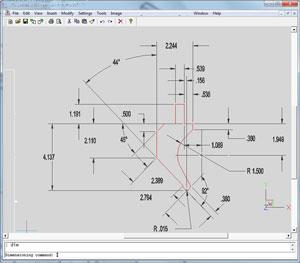
Figure 3: A 2-D shop sketch of a tool profile is shown.
An hour is a reasonable estimate of how long it would take an expert to do this from scratch. Some effort is required to do the initial modeling of the press brake tooling. The time-consuming part is the reverse engineering of the tooling. I recall it took about 15 minutes per tool to measure and enter all of the dimensions and angles for the gooseneck tooling. Once that was done, another 30minutes was spent creating an assembly of the brake tooling. Positioning the model and taking a screen capture took very little time.
I don’t want to quote prices, but let’s suppose that it costs the company $50 per hour to put an employee in front of a computer. Hypothetically, Figure 5 “cost” $50 to produce. Would I expend that effort to document every press brake setup in a job shop? Only in an economy where I’m paying people to lean on broom handles.
On the other hand, if you’re trying to explain to a customer how you can economically produce a stiffer bend, Figure 4 could be the best investment of the day.
If you’re a member of the Fabricators & Manufacturers Association and you’d like copies of the press brake tooling models shown in this article, let us know. We also should express appreciation to Amada America Inc. for publication of its excellent tooling catalog, which was relied upon heavily in the creation of the illustrations for this article.
Gerald would love to have you send him your comments and questions. You are not alone, and the problems you face often are shared by others. Share the grief, and perhaps we will all share in the joy of finding answers. Please send your questions and comments to dand@thefabricator.com.


The Fabricator is North America's leading magazine for the metal forming and fabricating industry. The magazine delivers the news, technical articles, and case histories that enable fabricators to do their jobs more efficiently. The Fabricator has served the industry since 1970.
start your free subscription
Easily access valuable industry resources now with full access to the digital edition of The Fabricator.

Easily access valuable industry resources now with full access to the digital edition of The Welder.

Easily access valuable industry resources now with full access to the digital edition of The Tube and Pipe Journal.

Easily access valuable industry resources now with full access to the digital edition of The Fabricator en Español.
In this episode of The Fabricator Podcast, Caleb Chamberlain, co-founder and CEO of OSH Cut, discusses his company’s...


