


Contributing Writer
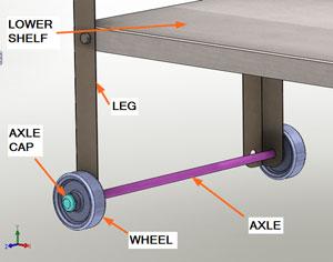
Figure 1a: The use of color can help other people to identify the components in the design quickly.
Pop quiz: Which form of documentation is most important?
In a way, it’s a trick question. I’ve apprenticed under gentlemen who could produce fine furniture and sculptures without any of the above. However, translating their one-offs to production of hundreds of copies requires organization. Organization requires documentation—of all kinds.
The documentation helps the project survive employee turnover. It also helps newcomers to the project familiarize themselves with what is going on.
A newcomer of another kind—the end user of the metal fabrication—will rely heavily on the owner’s manual. In this case, illustrations work a lot better than text.
(The usual disclaimer: If you’re not using the same 3-D CAD software as I am, then you’ll have to translate some of the terminology. However, the concept of parametric modeling is widely applicable.)
The 3-D CAD model can be used to generate a wide variety of documents. That’s why I generally focus on the model first and then move to complete the other forms of documentations. The charm of this type of software tool is that most of the documents that are based on a 3-D CAD model will update automatically if the model is revised.
One of the skills that CAD jockeys develop is good judgment about how much detail to put into the 3-D model. In general, if the feature is to be custom-made, then it needs to be modeled very accurately. By the same token, if the feature will influence something else that is custom-made, then accuracy will matter. On the other hand, if time and effort can be saved by approximating the feature without impairing the manufacturing or assembly of the project, then less detail is better.
It is one thing to imagine how a project will fit together and function. It is entirely another to see the design in 3-D space.
When I present a design for review, I usually use the 3-D CAD tool to focus the agenda of the meeting. I use rotations, cross sections, kinematic motion, and animations to explain how the design satisfies the design goals.
As a CAD jockey, you will make decisions about colors, textures, and realism. Sometimes photorealism is not an advantage. In Figure 1a I’ve used false colors to make it easier to identify components under discussion. By spending more time to render the image realistically (see Figure 1b), I make it easier to imagine what it would really look like. However, if I’m trying to explain something about axle caps, my audience will probably prefer Figure 1a as a way to quickly understand where the axle cap is.
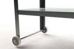
Figure 1b: The use of realism can be a mixed blessing: It looks great but takes time to produce and doesn’t always make things easier to understand.
Early design review meetings typically result in significant changes to the design, so don’t waste time on realism that might get discarded in the short term.
Screen capture is a quick and easy way to create static images for illustrations. Windows® has a built-in screen capture tool—ALT^PrintScreen—that will copy the screen to the clipboard. From there you could paste it into any other document.
To add notes and crop images like Figure 1a, I prefer tools like HyperSnap™ (http://www.hyperionics.com/) or Snagit® (http://www.techsmith.com/screen-capture.asp).
Whenever I can, I include handouts in my design review meeting. If a similar or competing product can reveal the function and flaws of a design idea, that item makes a great pass-around during the meeting. A stereolithographic reproduction or other form of a rapid prototype frequently can convey the merits of a design much more effectively than spinning a 3-D model around on a monitor.
One of the functions that differentiates various brands of 3-D CAD software is the generation of 2-D mechanical drawings. The ideal work flow is to make a 3-D CAD model and then have the software automatically generate the dimensioned drawing. The worst-case scenario is to re-create the 3-D design completely using a 2-D drafting package.
I’m not aware of a 3-D CAD tool that works perfectly in “automatic” mode. It seems that a view or cross section always presents itself that the software just can’t generate without help from a CAD jockey.
The software I’m using has the ability to display dimensions and annotations that are embedded in the 3-D model. That can be a benefit both in terms of consistency and labor savings. I must admit that when I’m designing a product, I seldom dimension the 3-D model in a way that makes sense in a manufacturing drawing.
In those situations where automatically importing details from the 3-D model is more of a hindrance than a help, the software should make it easy to populate your drawing with views and dimensions for those views.
Figure 2 is a drawing that took about five minutes to complete. It is a combination of imported annotations as well as manually positioned dimensions.
I’m particularly fond of including an isometric view on the drawing. It makes it clear whether 1st Angle Projection (European style) or 3rd Angle Projection (U.S.A.) has been used for the projected views. I like my isometric views to have tangent lines shown and hidden lines not shown. It is the opposite for the projected views—no tangent lines but all hidden lines shown. Why? Because press brake operators use the solid or dashed lines to verify the direction of the bend. Tangent lines make it more difficult to interpret the drawing.
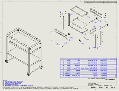
Your 3-D CAD software almost certainly will generate a table that lists all of the components that have been included in the 3-D CAD model. Such a table—a bill of materials—is frequently referred to by its acronym, “BOM.”
The BOM can be included in drawings (see Figure 3), exported as a spreadsheet, or even embedded in the 3-D model to aid in the data entry and validation of information in the table.
Purchasing, manufacturing, assembly, and maintenance personnel will rely on the BOM because it is one of the most important documents in a world of important details. An accurate and updated BOM is a competitive advantage.
This project was intended to span 12 articles. We’ve received several interesting suggestions from readers that we will try to address in upcoming articles.
Myriad modeling techniques were skipped or rushed, so even though this is the “last“ article dedicated to this grill project, we may refer to it again in the months ahead. If you would like to discuss a particular area of 3-D CAD modeling, you know how to reach us.
Gerald would love to have you send him your comments and questions. You are not alone, and the problems you face often are shared by others. Share the grief, and perhaps we will all share in the joy of finding answers. Please send your questions and comments to dand@thefabricator.com.


The Fabricator is North America's leading magazine for the metal forming and fabricating industry. The magazine delivers the news, technical articles, and case histories that enable fabricators to do their jobs more efficiently. The Fabricator has served the industry since 1970.
start your free subscription
Easily access valuable industry resources now with full access to the digital edition of The Fabricator.

Easily access valuable industry resources now with full access to the digital edition of The Welder.

Easily access valuable industry resources now with full access to the digital edition of The Tube and Pipe Journal.

Easily access valuable industry resources now with full access to the digital edition of The Fabricator en Español.
In this episode of The Fabricator Podcast, Caleb Chamberlain, co-founder and CEO of OSH Cut, discusses his company’s...


