


Contributing Writer
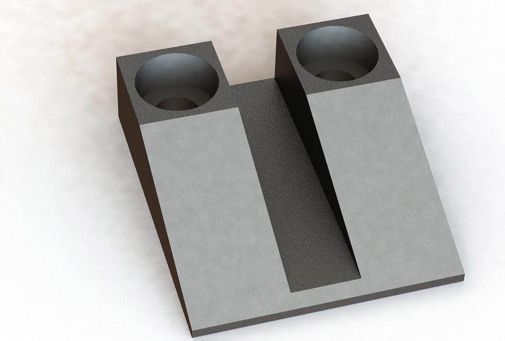
Figure 1a
An example of a product manufactured from steel is shown. Starting with a STEP file import, materials, environment, and camera were added. Starting with the rendering, the CAD jockey used an add-on to the 3-D CAD software to create this illustration.
I was once a job shop owner. Our mission was to add value to raw inventory, then to profitably deliver that valuable inventory to our customers.
In my case, the raw inventory was sheet metal. Over time routine material processing evolved and expanded to include machined billet and a little bit of plastic work. The investment in capital equipment matched or exceeded the customers’ expectation for precision and fine aesthetics.
In 2004, with 20 years of experience in fabrication, I retired and turned the shop over to better management. My interest had shifted from fabrication to design. The first customer of my industrial design practice is still sending me projects and has graciously allowed me to use one of its products in these illustrations.
Figure 1a is an image of a machined steel part. Fabricators in the machining trade often receive and use 3-D geometry in the process of developing machine control programs. To assist in verifying that the product coming off the mill is correct, a fabrication drawing may be prepared—Figure 1b, for example. This PDF has dimensions, finish requirements, and declarations of ownership that are otherwise difficult to show in imported 3-D geometry.
With the goal of having a paperless fabrication shop, a fabricator can rely on 3-D models, which have product manufacturing information (PMI) embedded in them. As a happy coincidence, most of the work required to prepare a 2-D fab drawing results from that PMI. Figure 1c shows some dimensional information, as well as a form with notes and written specifications.
Suppose that the paperless future has arrived! PMI, as hinted at in Figure 1c, has eliminated the need for 2-D drafting, as represented in Figure 1b.
The modern drafting department is now tasked more often with preparing illustrations as opposed to dimensioned line drawings. Either way, it is just a process for adding value to inventory.
Common ground exists between traditional drafting and product illustration. The inventory to work with is 3-D geometry. Experience with PDF/PMI helps with efficiency. The discipline required for preparing 2-D drawings is not much different from setting up camera shots on a consistent basis.
Figure 1a is a view of a 3-D model using a camera’s perspective, shadows from the environment, and resulting hues from materials and finishes. Setting up such a view can be accomplished in just a few minutes, but the mouse clicks and menus are not often used in 2-D drafting. It helps to practice.
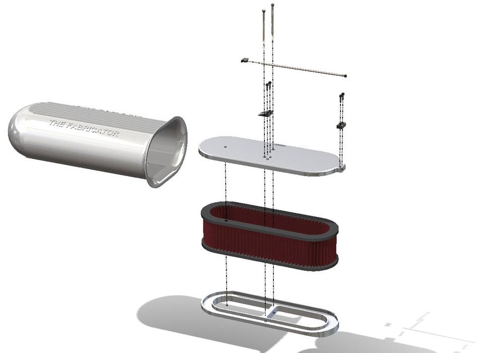
he assembled product illustrated in Figure 2a puts the ramp from Figure 1a into context. Several other parts are bolted and wedged together. Those items have been exploded in Figure 2b, which gives a hint about how the assembly goes together.
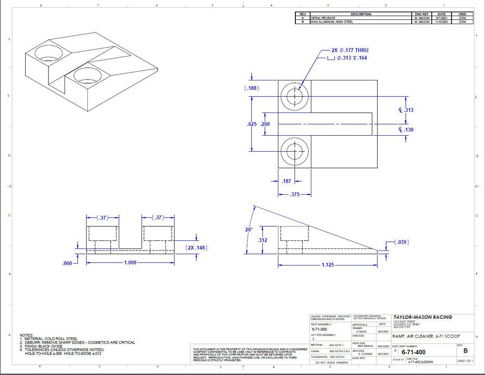
Figure 1b
An example of a 2-D PDF fabrication drawing is shown. The part from Figure 1a was dropped into the drawing template to reveal the product manufacturing information (PMI) embedded within the part.
Perhaps the most tedious aspect in preparing Figure 2b is the addition of path lines. One must click to place each end of each line. Even so, the preparation of exploded views is a routine skill from 2-D drafting.
With product illustration as the design intent, the twist is to plan and sequence the explode steps in 3-D CAD. When you are just making an exploded view for a 2-D drawing, the sequence of explode steps is pretty much irrelevant. Anticipation and plotting are subtle CAD skills that lend competitive advantage when making videos of animated assembly collapsing.
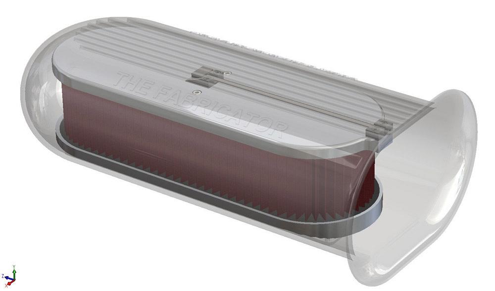
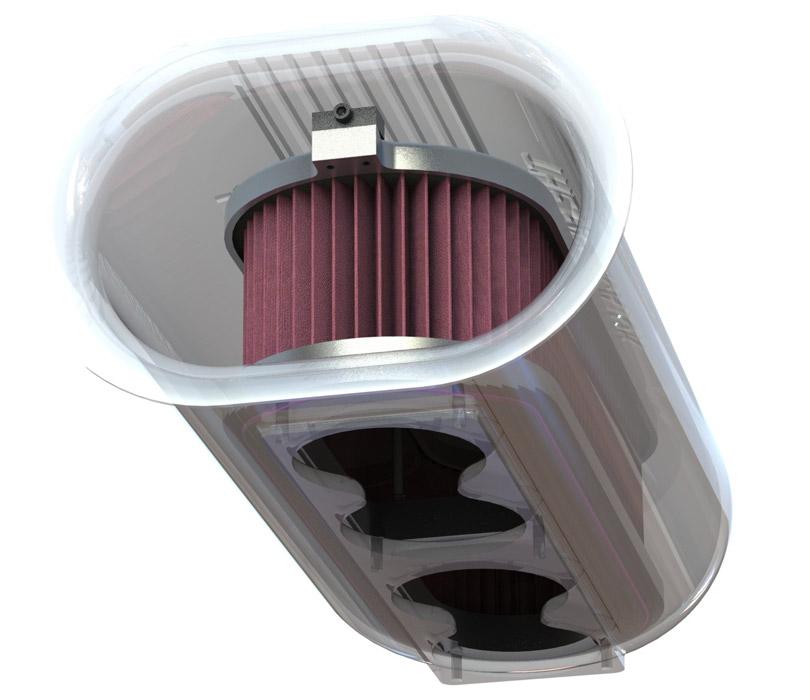
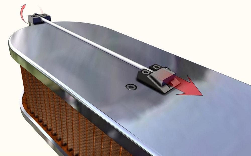
As another CAD tip, drama is sometimes useful for revealing details of an assembly. The dramatic example in Figure 3a is of transparent aluminum and a distinctive point of view. Figure 3a might be the exact image needed in a product brochure.
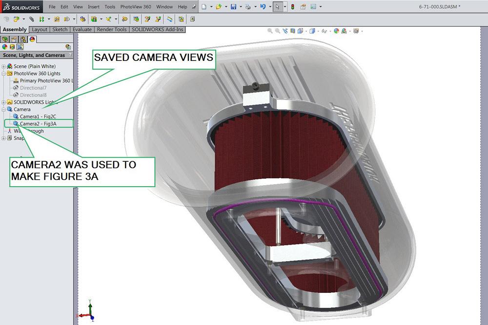
Here’s a CAD tip: Rename the camera and save its locked position. As the CAD model evolves and the illustration needs to be updated, just switch back to that saved camera position. In Figure 3b we see that two cameras have been set up. Camera2-Fig3A has been selected. Selection of a saved camera view is how the view of the model in Figure 3a may be instantly re-created.
Once the image is rendered, it needs to be saved in a digital format. This is not a new concept for the CAD jockey. However, anticipating how the digital image file will be used can be a real advantage for the seasoned pro.
Consider the task of making illustrations for a product brochure. When the design changes in CAD, we want the illustrations in the brochure to update. Efficiency is our competitive advantage. In terms of workflow, the core concept is to digitally link the 3-D geometry to the product brochure.
This is accomplished by using dedicated file names for the images. Both the Word document and the CAD rendering tool reference the same file for the image. CAD writes to that image file and Word reads from that image file.
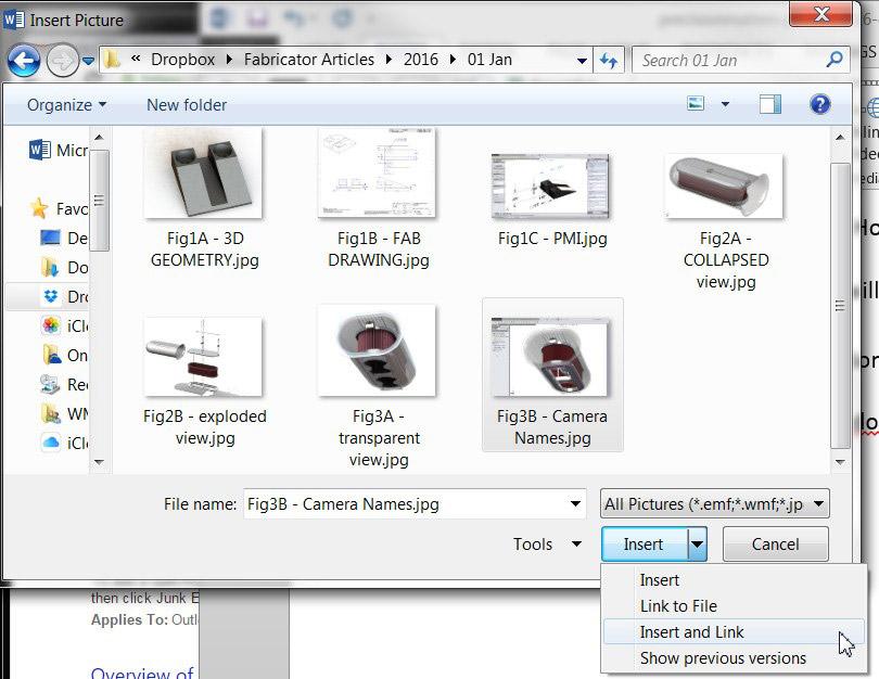
Here’s a Word tip: Insert pictures into the docx file using the Insert and Link option (see Figure 4). Since the Word docx must open a specific file in order to display the image, every time the docx file is opened, it automatically updates to show what changed in the CAD-produced images.
Here’s another CAD tip: Keep track of the file names that the docx is linked to. When you need to update an image in the brochure, just open the CAD model, switch to the saved camera view, and render the image to overwrite the previous image file. The final step is to open the docx file to refresh the brochure with the updated images.
Resuming my tale of shop ownership, I once had a very nice machine that had an interactive programming console. The operator’s convenience of programming the machine on the spot was offset by the downtime. This machine could either make product or it could be programmed, but not both. Investment in CAM software allowed offline programming for the next job while the current job was being completed. That separation of functions allowed for simultaneous instead of sequential completion of work.
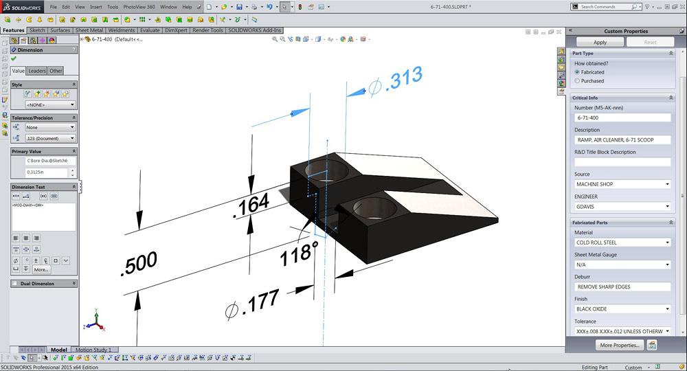
Figure 1c
The 3-D CAD software can be used to examine PMI. On the right is a data entry form for specifications and notations. All of the information required to fabricate this part is embedded in the model. In a paperless world, does this PMI make Figure 1b obsolete?
Similarly, with the right tools, the final product documentation can be prepared in parallel with the refinement of the product’s design. No need to wait until the bitter end of modeling work to start on the owner’s manual.
We’ll continue to use the 3-D CAD software for developing the 3-D geometry, preparing photo-realistic images, and demonstrating mechanical motion. The preparation of product documentation—web pages, illustrations, and step-by-step instructions—is an opportunity for teamwork, even if the “team” is just one person switching from one user interface to another.
Figures 5a and 5b resemble each other. One was created entirely with 3-D CAD software. The other shows 3-D geometry that was created from the 3-D CAD model.
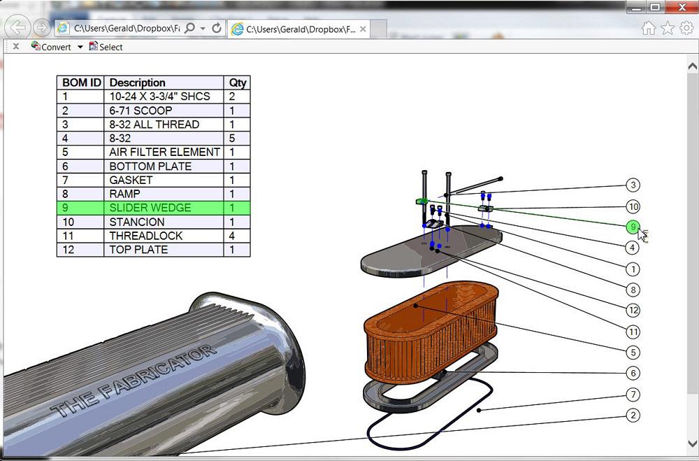
If you could open Figure 5c with a browser, you would find that it is interactive. When the mouse clicks on a part, it lights up along with the balloon and the line item in the table. You may click either in the table or in the graphics window to make a selection. It is as easy to generate as printing a PDF.
Figure 5d is a scene with several actors. A couple of them are arrows; most of them are 3-D geometry. The red arrows required less than a dozen clicks, and they are very easy to resize and configure.
3-D CAD is vital to engineering and design. Using those models to directly control fabrication machinery is a competitive advantage to manufacturing. Using those same models to create the product’s fab drawings is routine; we all love PDFs.
Design software has grown beyond the task of just making 2-D drawings. Plenty of software offerings now use 3-D models to document how the product is used. Some tools are more efficient than others, however.
Gerald would love to have you send him your comments and questions. You are not alone, and the problems you face often are shared by others. Share the grief, and perhaps we will all share in the joy of finding answers. Please send your questions and comments to dand@thefabricator.com.


The Fabricator is North America's leading magazine for the metal forming and fabricating industry. The magazine delivers the news, technical articles, and case histories that enable fabricators to do their jobs more efficiently. The Fabricator has served the industry since 1970.
start your free subscription
Easily access valuable industry resources now with full access to the digital edition of The Fabricator.

Easily access valuable industry resources now with full access to the digital edition of The Welder.

Easily access valuable industry resources now with full access to the digital edition of The Tube and Pipe Journal.

Easily access valuable industry resources now with full access to the digital edition of The Fabricator en Español.
In this episode of The Fabricator Podcast, Caleb Chamberlain, co-founder and CEO of OSH Cut, discusses his company’s...


