


Ask the Stamping Expert: How can we form holes smaller than the material thickness?

Q: We are using a progressive die to make a part that is 3.770 inch in diameter with 45 holes, each 0.172 in. in dimeter, on a 3.514-in. bcd [basic center diameter]. Our customer has asked us to change the material from 0.080-in. half-hard copper to 0.240-in. half-hard copper. Now the hole is smaller than the material thickness. Is there technology that will enable us to accomplish this project?
A: When it comes to producing high volumes, stamping is still the most economical approach.
We have been successful in stamping parts that require holes much smaller in diameter than the material thickness. In this case, working with copper certainly makes the challenge easier.
We attempt to do this only with a three-plate-designed tool because of the rigidity and guidance required for the application. The die chase on the bottom shoe holds the die buttons and raw material guiderails. The punch holder on the top shoe holds the punches, and the stripper plate guides the punches while resting on spring-loaded retainer pads that clamp the strip as the die closes.
The simplest way to pierce the hole is to use a punch with a larger diameter—for example, a 3/8-in. body—and turn down the tip to your pierce size. The body diameter must be substantial enough to absorb the compressive strain of the operation.
The disadvantage here is that the tip length must be at least as long as the sum of the material thickness, die penetration, and stripper guidance thickness, plus some clearance. That means the tip will be at least 0.500 in. long, and it will be service-intensive. Every time you service the punch, you will have to grind the tip diameter back on the body. The tip diameter will mutate, because every time you service, you touch-off to blend in.
Figure 1 shows a different approach using a ¾-in.-dia. nitrogen spring behind a quilled straight blanking punch. The dimensions show about 0.295 in. of unsupported punch body on contact. All the other specifications are just as important. The 0.0002 –in. clearances shown are critical. The angle on the punch head will prevent the head from breaking where it meets the body of the punch.
Three push pins of 1/8-in. diameter transfer the nitrogen spring force to the quill. The quill must be flush with the face of the stripper when the tool is open. Adjusting the cutting clearance to the high end will reduce piercing and stripping force.
Last, use standard, off-the-shelf M4 punch blanks. By adding a hard, precision-ground sleeve under the punch head you can sharpen the punch and shim behind the head. You don’t have to grind under the punch head to lower it for shimming; you can just grind the required amount off the sleeve.
In Figure 1, the force to pierce is 232,000 PSI, and the flexural yield strength of the p unch body is 508,000 PSI. You should have no problem in this application based on a 0.172-in. diameter.
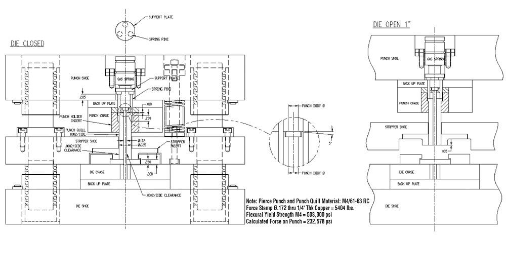
Figure 1
For this project, a 3⁄4-in.-dia. nitrogen spring behind a quilled straight blanking punch
would leave about 0.295 in. of unsupported punch body on contact.
You might be able to fit eight pierces in a progression. Assuming you have a 5-in. pitch and adding a station for piercing and piloting, you are looking at a 35-in.-long tool. Split the stripper plate in half at 1.5 feet.
It sounds like a lot, but you want it done right the first time. Service will be so simple, an apprentice can do it. Cost of maintenance also will be negligible.
About the Author

Thomas Vacca
Micro Co.
About the Publication

subscribe now

The Fabricator is North America's leading magazine for the metal forming and fabricating industry. The magazine delivers the news, technical articles, and case histories that enable fabricators to do their jobs more efficiently. The Fabricator has served the industry since 1970.
start your free subscription- Stay connected from anywhere

Easily access valuable industry resources now with full access to the digital edition of The Fabricator.

Easily access valuable industry resources now with full access to the digital edition of The Welder.

Easily access valuable industry resources now with full access to the digital edition of The Tube and Pipe Journal.

Easily access valuable industry resources now with full access to the digital edition of The Fabricator en Español.
- Podcasting

In this episode of The Fabricator Podcast, Caleb Chamberlain, co-founder and CEO of OSH Cut, discusses his company’s...
- Trending Articles
1
Capturing, recording equipment inspection data for FMEA

2
Tips for creating sheet metal tubes with perforations

3
Are two heads better than one in fiber laser cutting?

4
Supporting the metal fabricating industry through FMA

5
Omco Solar opens second Alabama manufacturing facility
