


Contributing Writer
Many specialty components can be used in dies, but the most commonly used are die plates, shoes, die sets, guide pins, bushings, heel blocks, heel plates, screws, dowels, and keys—all of which were explained in Part IV of this series. This article focuses on other common components—pads, retainers, and springs.
 |
| Figure 1 |
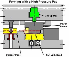
A pad is simply a pressure-loaded plate, either flat or contoured, that holds, controls, or strips the metal during the cutting and forming process. Several types of pads are used in stamping dies. Depending on their function, pads can be made from soft low-carbon steel or hardened tool steel. Contoured pads must fit very closely to the mating die section. Precision requirements determine whether the pads are positioned with guide pins and bushings or left unguided.
Stripper Pads/ Plates. Stripper pads are flat or contoured, spring-loaded plates that pull, or strip, the metal off the cutting punches. When it's cut, metal naturally tends to collapse around the body or shank of the cutting punches; this is especially true during piercing. The stripper pad surrounds the cutting punches and mounts to the upper die shoe. As the punch exits the lower die, the spring-loaded pad holds the metal down flush with the lower die section, which allows the cutting punches to withdraw from the sheet metal or piece part.
Often stripper pads are inserted with a small block of steel called a pad window. This pad window usually is small and lightweight and can be removed easily to allow the die maintenance technician to remove the ball lock-style pierce punch from the retainer without removing the entire stripper pad. Stripper pads also function to hold the metal flat or to the desired shape during the cutting process (Figure 1).
Pressure Pads/ Plates. During the wipe bending process, the metal must be held down tightly to the lower die section before the forming punch contacts the metal. Pressure pads must apply a force that is at least equivalent to the bending force. Most pressure pads use high-pressure coil or gas springs (Figure 1). When loaded with very high-pressure springs, contoured or flat pads also can form sheet metal. These pad types often are referred to as power punches (see Figure 2).
 |  |
| Figure 2 | Figure 3 |
Draw Pads. Draw pads control metal flow during the drawing process. In drawing, the amount of pressure, or downward force, exerted on the sheet metal determines how much metal is allowed to flow and enter the draw die cavity. Too much pressure may stop the metal from flowing and cause splitting; too little downward force may allow excess metal to flow inward and cause loose metal or wrinkling.
Draw pads, often referred to as binders or blank holders usually are made from hardened tool steel. They can be flat or contoured, depending on the piece part shape. Most drawing dies use a single draw pad; however, in special cases, some use two (Figure 3).
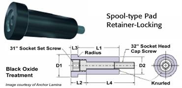
Spools, shoulder bolts, and keepers are used to fasten pads to the die shoes while allowing them to move up and down. They are secured to either the top or bottom die shoe with screws and often dowels for precision location. Of all of the components used for securing pads, spools are the most common, especially in larger dies (Figure 1 and Figure 4).
 |
| Figure 4 |
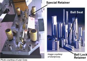
Retainers hold or secure cutting or forming die components to both the upper and lower die shoes. One of the most popular retainers is a ball-lock retainer, a high-precision, accurately manufactured die component that secures and aligns both cutting and forming punches. It uses a spring-loaded ball bearing to locate and secure the punches, which feature a precisely machined teardropor ball seat. The spring-loaded ball bearing locks into the teardrop shape and prevents the punches from coming out of the retainer.
 |
| Figure 5 |
The advantage of ball-lock retainers is that they allow the die maintenance technician to remove and reinstall punches quickly. The punch is removed by depressing the spring-loaded ball bearing and pulling up on the punch. Specialty retainers also can be made to hold and align irregular punch shapes, as well as headed-style punches and pilot pins (Figure 5).
Springs supply the force needed to hold, strip, or form metal. Many different springs are used in stamping dies. Spring selection is based on many factors, including the required force and travel, the spring's life expectancy, and, of course, cost. Among the most popular are gas springs, which, when filled with nitrogen, can supply a great deal of force. They also have an excellent life expectancy.
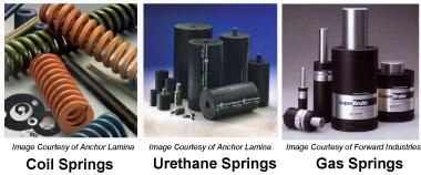 |
| Figure 6 |
Other types are coil and urethane springs, often called marshmallow springs (Figure 6). Coil springs are very popular when a reasonable amount of force is needed and budget constraints are present. Urethane springs work well in short-run or prototype stamping operations. They also are inexpensive.


The Fabricator is North America's leading magazine for the metal forming and fabricating industry. The magazine delivers the news, technical articles, and case histories that enable fabricators to do their jobs more efficiently. The Fabricator has served the industry since 1970.
start your free subscription
Easily access valuable industry resources now with full access to the digital edition of The Fabricator.

Easily access valuable industry resources now with full access to the digital edition of The Welder.

Easily access valuable industry resources now with full access to the digital edition of The Tube and Pipe Journal.

Easily access valuable industry resources now with full access to the digital edition of The Fabricator en Español.
In this episode of The Fabricator Podcast, Caleb Chamberlain, co-founder and CEO of OSH Cut, discusses his company’s...


