


Contributing Writer

Production stampers and die builders understand that the process of designing, building, troubleshooting, and maintaining a drawing die can be very difficult. Unlike metal cutting tools, drawing dies can take a great deal of time to develop, especially if the final part will be very deep and contoured.
When attempting to make such a difficult part, the diemaker and engineer must consider numerous factors that affect the metal flow. The key to controlling metal flow is to understand that the metal thickness changes during drawing. The drawing pad must compensate for these changes, so having a properly fit drawing pad is critical.
One way to ensure proper drawing pad fit is through the tuning process. It usually involves grinding the drawing pad (sometimes referred to as the binder or blank holder), the die face, and the cavity with respect to the compressive thickening and tensile thinning of the metal during drawing. This hand grinding process usually is followed by a great deal of stoning and polishing.
In the tuning process, spotting compound—a water-soluble ink used to fit die components together—is placed on both sides of the blank, and the blank is hit in the die between the die face and drawing pad surface. Ink missing from both sides of the sheet in the same area indicates coining or tight spots in the die. These areas then are ground away, and the process repeats until the drawing pad and die face fit perfectly.
After the drawing pad is fit to the die face, the draw spotting or tuning can begin. The blank is covered with spotting blue and is drawn into the die cavity slightly. As it draws, the corners begin to thicken and show up as coining on the die face. These areas must be ground to improve metal flow conditions. More grinding might be required to add clearance between the punch and cavity to allow for the thickened metal to flow. This process repeats until the part is drawn to its full depth. After the die has been fit, it can be stoned and polished.
Generations have passed down the misconception that the drawing pad must be spotted or fit as precisely as possible to the die face for the die to work properly. Many old-time toolmakers say the drawing pad surface should make contact with the die face, and at least 90 percent of the pad must fit perfectly.
While this is a good starting place, it’s not always the most effective approach in the long run. The draw pad should be ground and fit so that it controls the metal perfectly without squeezing or restricting it during the drawing process. If a metal flow restrictor is needed, a draw bead usually is more effective and consistent.
To understand the metal flow patterns in a contoured, shaped draw, you must have some basic knowledge of how metal flows during the drawing process. The first step is to understand how a simple cylinder cup is drawn.
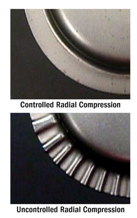
A cylinder starts out as a simple round blank. For the round blank to transform into the smaller cylinder shape, it must compress radially. In other words, for the larger-diameter blank to become the smaller-diameter cup, the metal must flow inward toward the centerline while it is compressing together (see Figure 1). If the compression is controlled, metal thickness will increase, and the part will have a flat flange. If the compression is not controlled, the flange will be severely wrinkled (see Figure 2).
The key thing to remember is that metal in compression has a great resistance to flow and a tendency to thicken.

Figure 1
For the larger-diameter blank to become the smaller-diameter cup, the metal must
flow inward toward the centerline while it is compressing together.
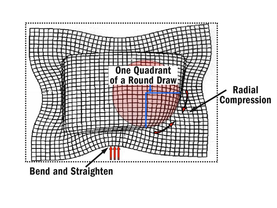
Each corner of a square draw is essentially one-quarter of a round draw (see Figure 3). In a round draw, the metal compresses radially as it simultaneously flows inward. The radial compression causes a resistance to flow in the corners of the square draw, while the inward flow causes the metal to compress.
If too much metal is forced into radial compression, the resistance to flow results in excessive metal stretching and possible splitting. However, if the blank is close enough to the radial profile of the punch, the metal will compress and flow inward, resulting in less metal thinning near the top of the shell and compressive thickening in the flange at the opened end of the shell.
The side walls of the drawn box are in bend and straighten deformation. Because there is little or no compression during this deformation mode, the metal flows inward with very little resistance. More resistance can be created by applying more blank holder force in this area or by adding draw beads.
Surprisingly, a flat-bottom part is not made with a flat draw pad. Remember, metal changes in thickness during the drawing process. If the draw pad and die face are perfectly flat, wherever the metal gets thicker, it will be pinched between the die face and drawing pad.
Where the part gets thicker usually is the area of greatest resistance to flow. A flat draw pad would, therefore, concentrate the most pressure in the areas that already have a great resistance to flow. A properly ground draw pad concentrates greater force on the side walls of the shell to keep the corners from wrinkling.


The Fabricator is North America's leading magazine for the metal forming and fabricating industry. The magazine delivers the news, technical articles, and case histories that enable fabricators to do their jobs more efficiently. The Fabricator has served the industry since 1970.
start your free subscription
Easily access valuable industry resources now with full access to the digital edition of The Fabricator.

Easily access valuable industry resources now with full access to the digital edition of The Welder.

Easily access valuable industry resources now with full access to the digital edition of The Tube and Pipe Journal.

Easily access valuable industry resources now with full access to the digital edition of The Fabricator en Español.
In this episode of The Fabricator Podcast, Caleb Chamberlain, co-founder and CEO of OSH Cut, discusses his company’s...


