


Graduate Research Associate - Center for Precision Forming
In the sheet metal forming industry, finite element (FE) simulation is an important tool for fabricators predicting metal flow, optimizing geometry, and selecting process variables before developing new dies. The accuracy of the simulation results depends highly on the accuracy of the input parameters and the boundary conditions used in the FE model. Input data includes the mechanical and thermal properties of the material, die geometry, forces, degrees of freedom, coefficient of friction, and ram speed.
One material property that affects simulation results significantly is flow stress (true stress/true strain curve) of the material. Flow stress determines the behavior of the material during the plastic deformation. Currently two methods are used for determining flow stress data: tensile test and bulge test.
The tensile test is a standard test for determining the elastic and plastic behavior of material under a uniaxial tensile condition. In the tensile test, a metal bar undergoes uniaxial tension up to fracture. The test can be used to determine such material properties as flow stress data, Young’s modulus, yield stress, ultimate tensile stress, uniform elongation, total elongation, and Lankford coefficient (r-value) (see Figure 1).
There are some limitations when using a tensile test to determine flow stress. The tensile test is a uniaxial tension test, so it provides the material behavior in uniaxial strain path. Also, the strain value at necking obtained from this test is small.
In contrast, in real sheet metal forming processes such as bending and deep drawing, materials deform in a different strain path, ranging from pure shear to biaxial tension. Also, the maximum true strain before fracture observed in the real stamping process is higher than what is obtained from the tensile test.
Therefore, in the simulation of processes such as deep drawing or bending, extrapolation of the flow stress data is required to determine the behavior of the material for the strain values higher than what is obtained from the tensile test.
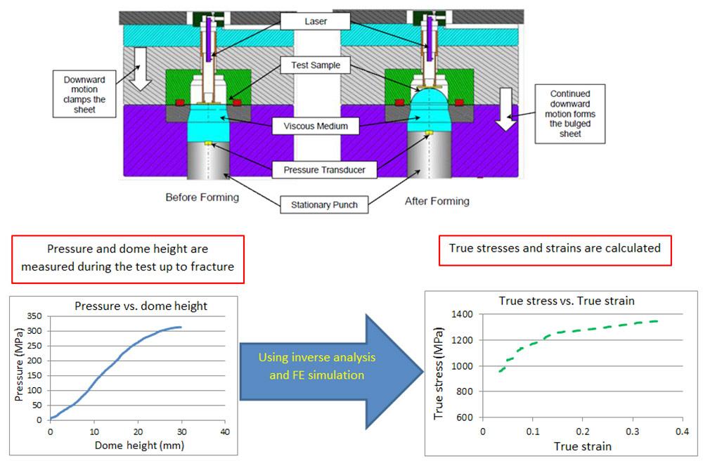
The hydraulic bulge test is used to evaluate formability and determine the flow stress data of the material. The stress state in the hydraulic bulge test is biaxial; therefore, this test can provide the flow stress data for higher strain values without localized necking compared to a uniaxial tensile test. The Center for Precision Forming (CPF) has used a viscous medium instead of hydraulic fluid, which reduces the complexity of the test and improves sealing.
The pressure for forming the material and the dome height are measured simultaneously during the viscous pressure bulge test (see Figure 2). The true stress/true strain data then can be calculated using the inverse analysis method and database created from the FE simulation.
For large strain values, the flow stress data obtained from the bulge test is more accurate than extrapolation of the tensile test results. Consequently, the simulation results should be more accurate when using flow stress data from the bulge test compared to the tensile test.
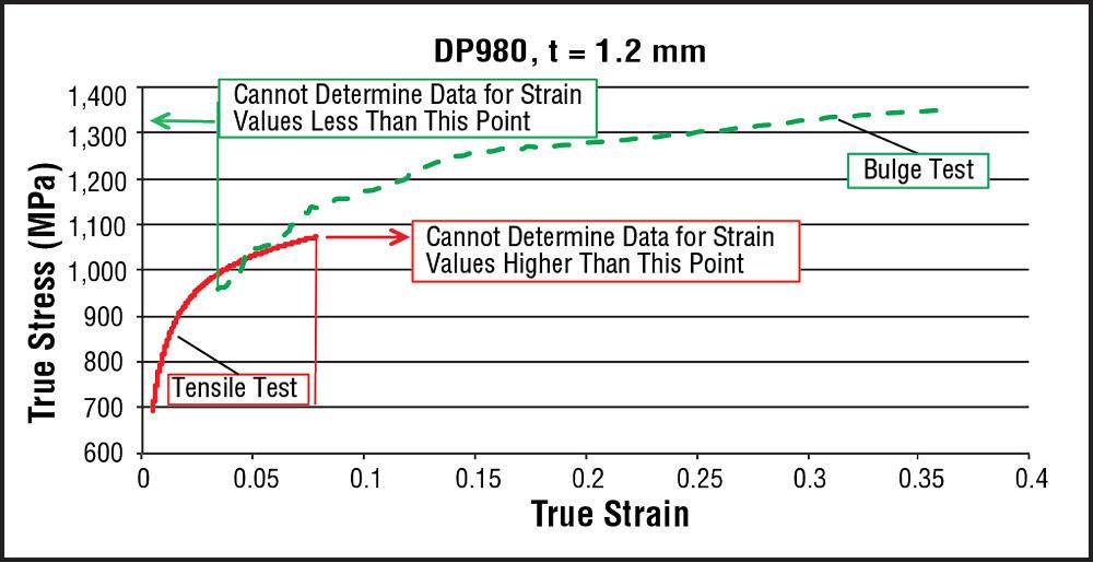
The bulge test cannot provide flow stress data for low strain values close to the yield point (see Figure 3), so when the data is used in simulation, the yield point of the material isn’t defined accurately. This can affect the elastic behavior of the material in the simulation and cause inaccurate simulation results, especially when springback must be predicted.
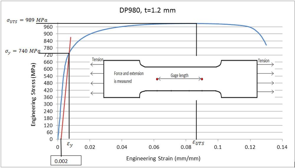
Figure 1 The tensile test determines such material properties as Young’s modulus, yield strength, total elongation, and uniform elongation.
In a current study at CPF, researchers have proposed a new method for determining more accurately the flow stress data from the actual yield point up to the largest strain values obtained from the bulge test. This method combines the results from the bulge and tensile tests.
The bulge test can provide more accurate flow stress data at high strain values, while the tensile test can provide accurate material properties up to the yield point. Combining the tests thus can provide more accurate flow stress data from yield to the strain at fracture in the biaxial stress condition.
The result of the tensile test is engineering stress-strain data. To be able to combine this with the bulge test results, the engineering stress-strain values must be converted into true stress-strain values using the following formula:
Since the tensile test provides the uniaxial yield stress, this value is converted to the biaxial stress using the following equation:
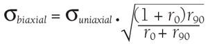
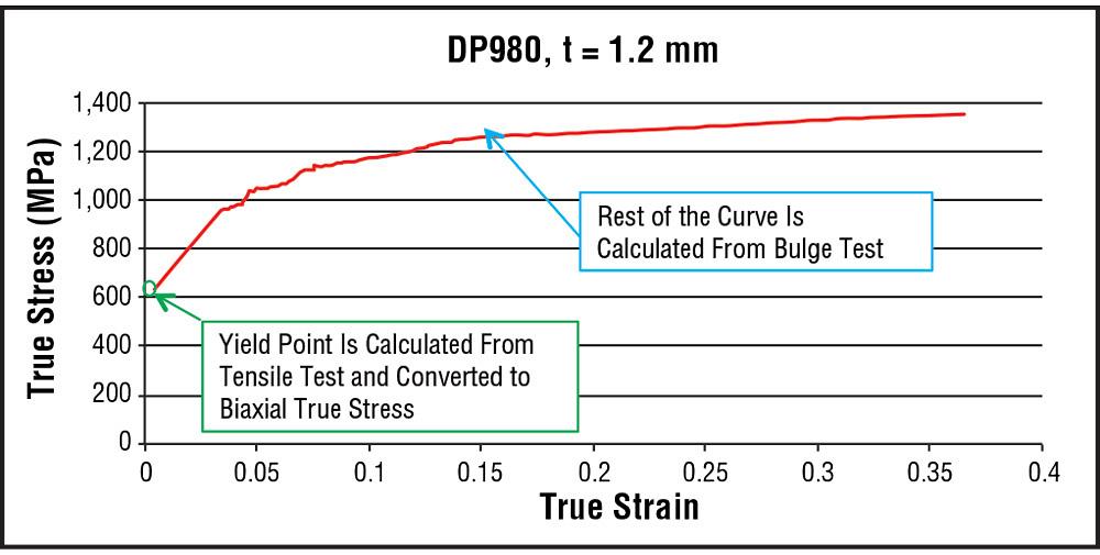
where r0 and r90 are the Lankford coefficient showing the anisotropy of the material in rolling and transverse direction, respectively. The biaxial yield stress is the starting point of the flow stress data. This point is included in the data point obtained from the bulge test, and the curve is fitted into these data points (see Figure 4).
With this method, the flow stress data includes the real large strain values from the bulge test, as well as the accurate yield point obtained from the tensile test. CPF uses this method extensively to determine the flow stress of a variety of advanced, high-strength materials, including CP800, DP590, DP980, TRIP1180, TWIP900, and TWIP980.
Acknowledgment: The tensile data discussed in this article was generated by Honda R&D, while the bulge tests were conducted at the Center for Precision Forming.

Professor Emeritus and Director - Center for Precision Forming


The Fabricator is North America's leading magazine for the metal forming and fabricating industry. The magazine delivers the news, technical articles, and case histories that enable fabricators to do their jobs more efficiently. The Fabricator has served the industry since 1970.
start your free subscription
Easily access valuable industry resources now with full access to the digital edition of The Fabricator.

Easily access valuable industry resources now with full access to the digital edition of The Welder.

Easily access valuable industry resources now with full access to the digital edition of The Tube and Pipe Journal.

Easily access valuable industry resources now with full access to the digital edition of The Fabricator en Español.
In this episode of The Fabricator Podcast, Caleb Chamberlain, co-founder and CEO of OSH Cut, discusses his company’s...


