


Contributing Writer
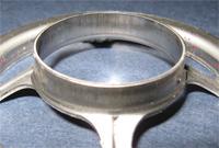
Figure 1 Click to view image larger A good extrusion die design.
Editor's Note:This is Part II of a two-part series. Part I explored the effects of the working material as well as the edge condition of the prepierced hole. This article discusses the effects of die design and the use of ironing and preforms.
Die design and build is a critical part of a successful extrusion process (see Figure 1).
Extrusion Punch. The extrusion punch should be made of highly wear-resistant tool steel—powdered metal (PM) preferably—or solid carbide material.
The punch should be polished linearly to a mirrorlike surface finish.
Relieve the punch after extruding the straight section to allow for lubricant to settle into the negative portion of the punch. This will help to lubricate the punch on the return stroke during punch stripping.
The punch should contain a pilot that is slightly smaller in diameter than the extrusion's pierce hole. This helps to concentrically locate the hole in the center of the extrusion die, resulting in a fairly uniform flange height.
The Upper Stripper Pad. The pad should have only enough spring pressure to strip the extruded metal from the punch; excessive pressure may cause the extrusion to be crushed between the upper and lower pressure pads. Light coil springs often are used.
The Lower Pressure Pad. Use a high-pressure gas spring under the pad. A good rule of thumb is to use approximately 600 pounds per linear inch around the extrusion punch.
For example, let's say your extrusion punch is 1 inch in diameter. This means that it has a 3.141-in. circumference. Multiplying 3.141 in. by 600 lbs. equals 1,884.6 lbs. A single 1-ton (2,000 lbs.) cylinder is sufficient.
The reason for using such a high-pressure spring is not to simply strip the extrusion from the lower die but to convert the die into a drawing operation as well as an extruding operation. At the beginning of the stroke the metal is pinched very tightly between the face of the extrusion punch and the high-pressure pad. This causes metal to be pulled from the apron area around the extrusion, creating a drawing effect. It also helps to distribute the strain more evenly.
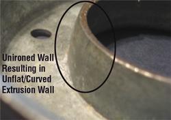
Figure 2Not tapering the lower die may result in a nonuniform-diameter extrusion with a curled or uneven wall.
In addition, as the metal begins to pull away from the pilot point in tension, it is deformed in a strain state commonly referred to as bilateral or biaxial stretch. Very simply put, steel can stretch more in two adjacent directions than it can in a single direction.
I have often solved many extrusion problems such as splitting simply by replacing a low-pressure coil spring with a high-pressure gas spring.
The pad should be made of premium tool steel. It should be polished in the direction of metal flow.
Lower Die / Matrix / Button. The matrix, or lower die, also should be made of premium tool steel. The lower die must have a true, complete, polished drawing radius—the larger the better.
Taper the lower button to compensate for the natural thinning that will occur during the extruding process. This process is critical. To squeeze the extrusion walls uniformly, you must compensate for the difference in metal thickness from the top of the extrusion to the bottom. Not tapering the lower die may result in a nonuniform-diameter extrusion with a curled or uneven wall (seeFigure 2).
This is where a technique called ironing—vertically squeezing the metal between the punch and the die to increase the surface area—comes in. Iron the wall slightly—1 to 2 percent of the metal's original thickness should be sufficient. This will help to refine the extrusion.
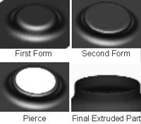
If you use these techniques, a properly ironed extrusion should result (see Figure 3). If failures such as splitting still occur, your extrusion may require preforming operations first. Preforming is a metal stretching or drawing operation that is used when more metal is needed in the area to be extruded.
A very tall extrusion can be created using multiple drawing operations before the actual extruding process. However, this is not a "true" extrusion. It is, in fact, a draw reduction that looks like an extrusion. The number of preforms required varies depending on the height of the extrusion as well as the metal type and thickness (seeFigure 4).
Keep in mind that certain metals, especially thin, ultrahigh-strength metals, by their nature have very poor stretchability. Trying to create a tall extrusion with these metals can be very difficult and sometimes nearly impossible.
Until next time � Best of luck!


The Fabricator is North America's leading magazine for the metal forming and fabricating industry. The magazine delivers the news, technical articles, and case histories that enable fabricators to do their jobs more efficiently. The Fabricator has served the industry since 1970.
start your free subscription
Easily access valuable industry resources now with full access to the digital edition of The Fabricator.

Easily access valuable industry resources now with full access to the digital edition of The Welder.

Easily access valuable industry resources now with full access to the digital edition of The Tube and Pipe Journal.

Easily access valuable industry resources now with full access to the digital edition of The Fabricator en Español.
In this episode of The Fabricator Podcast, Caleb Chamberlain, co-founder and CEO of OSH Cut, discusses his company’s...


