


Contributing editor
JST, Waukegan, Ill., installed Cognex’s In- Sight® 5600 / 5705 series vision system to maintain high part quality levels and tight dimensional tolerances to achieve zero defects. The In-Sight 5600 model has a resolution of 1,600 x 1,200 pixels and an image acquisition time of 15 frames per second. Its 60- by 110- by 80-mm body fits within the tight confines of the press area. Photo courtesy of Cognex, Natick, Mass.
Trial and error is a difficult, time-consuming, and costly way to find the sources of problems in a stamping operation. Also, adjustments and analysis done on the front end usually save time and money by several magnitudes compared to doing so on the back end.
Stamping die designers, engineers, production managers, and operators have new tools to help them make changes on the “easy side of the press” to prevent problems from occurring after the dies have been built and operations have begun.
When errors do occur, their cause can be difficult to diagnose. Some can be detected only by seeing faster than the naked human eye can capture and in a closer proximity than is safe. What then?
Too, many problems occur because a material is out of spec, or can be avoided with better knowledge of the work material’s metallurgy.
Here are some new and effective approaches.
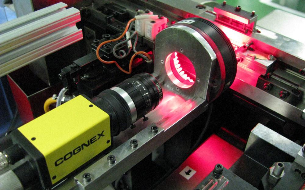
Vision systems comprising a camera and sensors positioned in strategic areas of a press operation are being used with increasing frequency to inspect, identify, gauge, and guide parts (see Figure 1). They can inspect for assembly errors, surface defects, damaged parts, and missing features as well as identify the orientation, shape, and position of objects and features for robotic loading and unloading. They can gauge parts to check critical dimensions and measure components for sorting and classification processes.
Self-contained, industrial-grade vision systems combine a library of advanced vision tools with high-speed image acquisition and processing.
The latest crop of vision systems are smaller and faster with higher resolution than their predecessors.
Cognex Corp. recently introduced its In-Sight® Micro series smart cameras, a new family of compact, stand-alone vision systems. The ultracompact vision system is suitable for applications where press space is a premium.
Compact in-die and in-press vision cameras and systems can be deployed into tight spaces and hard-to-reach areas in presses and material handling robots. They can be deployed almost anywhere on the production line for guidance, inspection, gauging, and identification.
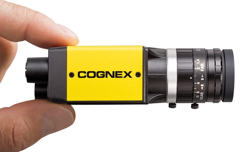
Figure 1
The In-Sight Micro 8000 series measures 31 by 31 by 63 mm and includes Power over Ethernet,
minimizing cabling and making it suitable for integration. Photo courtesy of Cognex.
“As press line speeds increase, manufacturers demand greater accuracy, larger fields of view, and faster vision tool performance without a PC on the factory floor,” a company spokesperson said.
JST, Waukegan, Ill., is a global manufacturer of more than 30,000 different types of electrical and electronic connectors. They include surface-mount, flat flexible circuit, crimp wire-to-board, header, flat cable, wire-to-wire, board-to-wire, board-to-board, power-to-supply, wire-to-board, EMI shielded, and IC memory card connectors. For most standard terminals, JST stamps oxygen-free copper, which has high electroconductivity and inherent toughness and can be brazed with no chance of hydrogen embrittlement. Its standard products are galvanized and treated with a special method that ensures maximum adhesion of electroplating, further reducing electrical resistance and enhancing corrosion resistance.
The company’s new LEK series connectors provide a space-saving and low-profile connection for LED lighting and reliable contact construction for high-density applications. Any misalignment between the horizontal connections and the printed circuit boards (PCBs) is absorbed by the LEK plug and receptacle. The PCB-mounted contacts are stamped of tin-plated copper alloy. The spring contact in the receptacle is designed with a hook that provides a secure locking system. This positive-locking feature helps to ensure high retention force while providing ease of assembly.
JST had maintained the necessary demanding quality standards and tight dimensional tolerances by devoting considerable time and resources to manual inspection. “We spent a lot of time continually checking these parts,” said Nate Hoselton, JST facilities manager. “Often problems were not detected until a day or two after the parts had been overmolded. In that case, we had to go back and reinspect a considerable number of parts. It was sometimes difficult to identify the problem after the fact.”
It typically took several days and about $1,500 to investigate each nonconformance, Hoselton said.
The manufacturer implemented a Cognex In-Sight vision system that measures parts to an accuracy of 0.1 mm (see lead image). The vision system identifies variations faster than human inspection, making it possible to adjust machine parameters quickly enough to avoid defects. The result is that the number of nonconformances in the latest measurement period was reduced to 0 parts per million (PPM), well below its Six Sigma quality benchmark of 3.4 PPM.
JST managers attribute this to the implementation of the machine vision system. “Quality is by far the most important factor in our company’s success,” Hoselton concluded. “Machine vision has helped us make significant improvements by helping us detect variation faster so we can make corrections before defects occur.”
A vision system can be as simple as installing a so-called high-speed action camera. These cameras are made to record sports action, so they operate at 100-plus frames per second. Because they are designed to record underwater, the camera comes in a sealed case that protects it from water and oil.
Armor Contract Manufacturing, Elkhart, Ind., takes a comprehensive approach to manufacturing. All individual parts and components, either designed by its engineers or based on provided designs, can be made to spec and then fabricated into subassemblies or complete products, including finishing.
Its stamping department had problems with parts not ejecting fast enough from a press. To analyze the problem, it took a comprehensive approach as well. Using a GoPro high-speed action camera, the crew recorded what was happening in the die, then viewed what was recorded at a lower speed to detect the cause (see Figure 2).
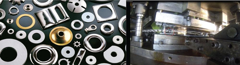
Figure 2
Armor Contract Manufacturing stamping staff was having trouble with washer parts not ejecting properly on an intermittent basis. The
manufacturer used a GoPro® high-speed camera to diagnose the cause of the problem. Photo courtesy of Armor Contract Manufacturing,
Elkhart, Ind.
“Our high-speed horizontal press stamps six washers at a time at 160 strokes per minute. It throws out a lot of washers just ridiculously fast,” said Wally Nels, information technology manager. “What happened was that every once in a while—about every 150 strokes—we would get a bent washer. It would happen so fast you wouldn’t even see it. We weren’t sure when and where it was happening.”
The standard procedure when a part or press malfunctions was for the maintenance crew to gather around the press and cycle it once to see where the problem was. In this case, the defect didn’t occur every press cycle, so it was difficult to catch the error in action. In addition, for safety reasons, a crew member could not get close to the die while it was cycling.
“So the two beauties of the camera we used are that it can record 120 frames per second and that you can place it within a foot of the die where you could never put your head safely,” Nels said. “We could detect things we couldn’t see with the naked eye.
“From our standpoint, it was an inexpensive but effective solution,” Nels added. “We tried it and it worked great.”
Sometimes problems can be prevented at the design stage. Die designers can determine manufacturability and feasibility to prevent die collisions.
A new module within ESI’s PAM-STAMP simulation software, Die Starter, is designed to enable decision-making early in the product design and styling phase to enhance manufacturing feasibility and reduce defects. It automatically generates an initial die face design from minimal input parameters, then generates a formability analysis (see Figure 3). Engineers can assess the manufacturing feasibility of the part drawn from CAD data.
The software improves on the initial die face using a mathematical optimization algorithm based on feasibility criteria to prevent splits and wrinkles. It automatically generates geometric modifications of the binder and addendum. This optimization capability minimizes material usage while reducing or eliminating high and low thinning.
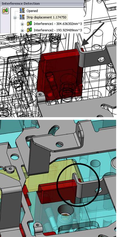
Accurate Die Design’s LOGOPRESS3® 3-D die design software includes debugging tools such as dynamic interference detection. Some common problems designers make when trying out a metal stamping die for the first time in a punch press are missing clearances and stock strip feeding problems, a company spokesperson said.
For example, on a part that has a tab on it that has been formed down, the die designer allows enough strip lift to raise the tab above the die block to clear it as the strip advances. But it is easy to miss something else downstream in the die, such as a form up die insert that the tab will hit as it feeds, because it needs to be lifted higher than the form up insert to clear it and not just to be higher than the die block.
A die designer can use LOGOPRESS3’s tool animation command to simulate the die operating in the press. This includes the strip lifting and advancing. While in this tool animation command, by activating the dynamic interference detection option, the software can detect collisions that would occur as the die is cycling so that the mistake can be caught at the design stage. The setup required to do this tool animation is just a matter of seconds according to the company spokesperson. If there are pilot lifters, cams, and so forth in the die that the user wishes to animate with this command, then a bit more set up is required (see Figure 4).
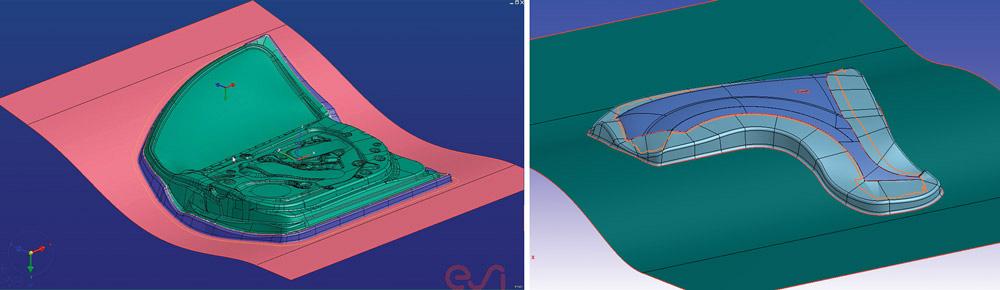
Figure 3
Die designers can model the design of the
initial die face outer fender and develop
flanges using ESI PAM-STAMP. Also, the
inner door initial die face is generated
automatically using the software. Image
courtesy of ESI Group USA, Hartland, Wis.
Jim Harsa of Universal Metal Products in Wickliffe, Ohio, uses the interference detection module in Logopress3, which allows him to simulate the tools running in the press on-screen. “I can view the strip coming through the die in each station, where anything is going to interfere, and what I need for clearance.”
Chris Metzel, of IMS Buhrke-Olson, Arlington Heights, Ill., found the dynamic interference detection module to be helpful as well. “The interference detection [tool] caught dimple clearances and a c’bore depth mismatch between my T.R. Jones pins and my stripper bolts—worth it right there for me. It also caught a tap depth that was not deep enough for the chosen screw length, which I thought was incredible.”
Verifying a metal’s grade and knowing its content has become more critical, as metal stampers are tasked with heroic acts of forming stronger yet thinner metals for the automotive, aerospace, electronics, and medical segments. Often they’ve had a forming problem attributed to “bad metal” and variations in its content from one end of the coil to another. Because metal properties vary, how stampers form them must vary also. Devices that provide rapid metal verification help stampers ensure quality and prevent forming issues attributed to “bad metal.”
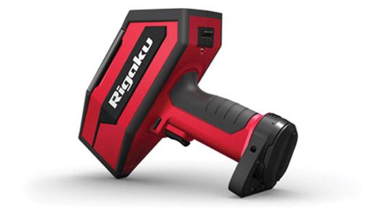
Rigaku Analytical Devices recently introduced KT-100 Katana™, a hand-held laser-induced breakdown spectroscopy (LIBS) analyzer for determining material composition (see Figure 5). LIBS is traditionally a lab-based technique. The hand-held device offers a new way to quickly verify a metal’s grade before it is fed into a press. It can help stampers identify light elements in metal and alloys, including aluminum grades 1100, 6061, and 6063.
Using the device, stampers can verify alloy grades at the pull of the trigger. The alloy grade is clearly displayed on the screen along with the percentages of individual elements contained within the material.
Applications include quality assurance and positive material identification. The technology can also help stampers sort scrap for optimal recycling and recovery returns.
Accurate Die Design, www.accuratediedesign.com
Armor Contract Manufacturing, www.armorcontract.com
Cognex Corp., www.cognex.com
ESI Group, www.esi-group.com
GoPro, www.gopro.com
IMS-Buhrke-Olson, www.buhrke.com
JST, www.jst.com
Rigaku Analytical Devices, www.rigakuanalytical.com
Universal Metal Products, www.universalmetalproducts.com

The Fabricator is North America's leading magazine for the metal forming and fabricating industry. The magazine delivers the news, technical articles, and case histories that enable fabricators to do their jobs more efficiently. The Fabricator has served the industry since 1970.
start your free subscription
Easily access valuable industry resources now with full access to the digital edition of The Fabricator.

Easily access valuable industry resources now with full access to the digital edition of The Welder.

Easily access valuable industry resources now with full access to the digital edition of The Tube and Pipe Journal.

Easily access valuable industry resources now with full access to the digital edition of The Fabricator en Español.
In this episode of The Fabricator Podcast, Caleb Chamberlain, co-founder and CEO of OSH Cut, discusses his company’s...


