


Director
Editor's note: This is the first part of a two-part article that examines tube bending defects, possible causes, and suggested remedies. Part I discusses surface defects; Part II covers other defects, such as wall thinning, ovality, buckling, and fractures.
Analyzing tube bend defects and taking the proper corrective action require close observation skills and an understanding of all the variables in the bending process. Correcting for defects requires some detective work on your part because there may be more than one cause for the defect, especially as more tools are added.
Before any discussion regarding correction for tube bending defects can take place, it is important that you understand the bending process. In the dynamics of bending, several things are happening at the same time, and it helps to evaluate causes of defects in relationship with these variables. The five main variables are the bending machine, tools, setup, material, and lubrication.
First, the bending machine comprises the devices creating the forces for bending, the control mechanism that positions the tube, and the devices for holding the tools during bending.
Second, the tools themselves are a variable, in terms of the condition of the mounting surfaces and tube grooves.
The third variable is the setup of the tools relative to each other and the forces the machine creates during clamping and bending.
The tube material variable is both dimensional and metallurgical—the mechanical properties of the tube metal such as hardness and strength.
The last variable is lubrication. It is necessary to lubricate stationary tools such as the mandrel and wiper die during bending and to have a film barrier between these tools and the tube.
Four main categories of bend defects are surface defects, wall thinning, ovality, and buckling.
You can remove some of these defects by cleaning tools or adjusting the setup. To fix others, you may require additional tools to help support the forces on the tube during bending. Sometimes when you try to correct one defect, a second defect occurs, and you may or may not have eliminated the original defect.
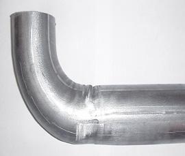
Impressions and Indentations in Clamp Area. In some cases, the clamping die leaves an impression on the tube from tube groove serration or preparation (see Figure 1). This usually happens with new tools. This can be considered a defect, depending on the finished application.
 |
| Figure 1 These indentations are from sharp edges of the clamp die and clamp die insert or serrations in the clamp die that are designed to improve the grip action. |
The fix: The correction is to polish the clamp surfaces and/or reduce the clamp force. Also check the dimensions of the tube groove in relation to the tube. Sometimes heat treatment during the manufacturing of the tools closes the groove, which can then pinch down on the tube.
Gouges in the Clamp Area. Observe if the gouge mark is on the clamp die side, bend die side, or from both sides. Is the gouge mark just at one point of the tube, or does it run the full length of the clamp? Is the gouge mark just at the top or just at the bottom of the tube?
The fix: Check the dimensions of the tube and tube groove. If the gouge mark is on both the clamp die and bend die insert side of the tube, it is possible that the tube diameter is too large for the tube groove. If the gouge mark is on just one side and on the top and bottom, it is an indication that the groove in that tool is too small. Check the tube purchasing specifications against the tool manufactured specifications.
The other fix: If the gouge mark is at a point corresponding to a corner of the clamp die, check for clamp slippage during bending. Tube slippage during bending can be an indication that the tube grooves are worn or that not enough clamp force is being applied. Aggressive clamp die forces also may gouge a corner of the tube. Try backing off on clamp die pressure, and make sure that the tube does not slip during bending. Also check to see if the clamp corner is too sharp. Clamp die corners usually are rounded off slightly to avoid this gouging caused by sharp clamp corners.
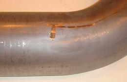 |
| Figure 2 If the gouge runs the length of the clamp and is at either the top or bottom of the tube, it usually indicates that the tools are not lined up properly. The single transverse gouge was caused by material buildup on the clamp die. |
The other, other fixes: If the gouge runs the length of the clamp and is at either the top or bottom of the tube, it usually indicates that the tools are not lined up properly (see Figure 2). Generally, a clamp die will "float up" with misaligned tools and not cause a gouge; however, if the clamp die is set too high in relation to the bend die groove, it cannot be forced down and will force the tube up instead. This shows up as a gouge on the bottom of the tube on the clamp die side and sometimes as a gouge on the top of the tube on the bend die insert side.
When setting up the clamp die to the bend die, it is not always easy to get the two grooves lined up perfectly. If you must make a judgment, err on the side of adjusting in the direction opposite the way the clamp die floats. This way it will self-align during clamping.
Whether a gouge appears on the bend die side depends on whether the tube is already inside the bend die clamp area at the time of clamping. Gouges caused by a misaligned clamp die generally continue into the bend for a short distance and then stop because the pressure die alignment takes over.
Also check for tube material buildup on the tool tube groove edges. Sometimes the coating on coated materials such as aluminized steel flakes off and builds up on tools.
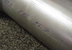
Short Surface Scrape Marks. If a tube slips during bending, it leaves a series of short, longitudinal surface scrape marks in the clamp area (see lead image). The scrape marks do not appear the full length of the clamp area. In most cases, they are evident only sporadically in the clamp area. The longer the scrape mark, the more slipping has occurred. Tube slipping can cause three different problems. The first is the obvious dimensional change for the location of the bend in the tube length. The second is that it makes gouges that appear as surface defects (see previously discussed remedy). The third generally is associated with tubes that have higher ratios of tube OD to wall thickness and/or smaller D of bends, which causes buckling in the inside bend radius. D of bend is the bend centerline radius divided by the tube OD.
The fix: The first and most logical correction for tube slipping during bending is to adjust the clamp die so it is closer to the bend die, which increases clamp die forces against the tube. You always should adjust the clamp die with a tube in the tube groove of the bend die.
The other fix: Carefully observe the movement of tools during clamping. A bend die that tilts up during clamping indicates tool mounting wear or that the bend die vertical clamping is not tight enough. Check for wear of the key fit and die boss mounting surfaces. These should be snug fits without rounded corners. Also check to see if the top and bottom surfaces of the clamp die and bend die insert are touching. This indicates either worn tube grooves or an undersized tube OD. If they are touching during clamping, then increasing clamp pressure only transfers force through the tooling and not the tube.
The other, other fixes: One of the most common causes of slipping is clamp length that is too short to create the frictional force to hold the tube. Many variables determine the proper clamp length, including the D of bend, wall factor, material, pressure die assist, and boost on the tube end during bending. Two rules of thumb for clamp length are: For 3D and larger bends, the clamp length should be 2x OD; for 2D and tighter bends, thin-walled materials, and stainless steels, the clamp length should be 3x OD or longer. If this isn't possible, then the extra force required to prevent slipping will create surface defects in the clamp area, generally because these forces squeeze the tube OD smaller than the tube nominal OD. This may even result from clamping the mandrel inside the tube.
Another factor that may cause slipping is a pressure die that is adjusted too tightly against the tube. Even if you are using pressure die assist, it may not be strong enough to overcome the force against the tube, so it pulls the tube back during bending, causing slipping. To correct this, back off on the pressure die clamping pressure.
If you are using a wiper die that is set too close to tangent, resulting in an improper rake angle, the wiper die and pressure die forces against the tube act like a clamp to prevent the tube from going forward during bending. This causes the tube to slip during bending. To correct this, reset the wiper die position.
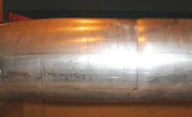 |
| Figure 3 Excessive clamping pressure can make a deep indentation around the tube in the area between the clamp die and pressure die. If the indentations are very deep, it is possible that the clamp is set too close to the bend die. |
Finally, check the mandrel and wiper die lubrication. Very tight D of bends and high-wall-factor tubes require very good lubrication to prevent these tools from dragging on the tube during bending. Lubrication must be consistent, good-quality, and appropriate for the metal type.
Deep Indentations Between the Clamp Die and Pressure Die. A deep indentation around the tube in the area between the clamp die and pressure die can be caused by excessive clamping pressure (see Figure 3). If the indentations are very deep, the clamp may be set too close to the bend die. Generally, a trailing corner indicates which die is causing the problem. If this corner is going into the bend, the pressure die is set too tight against the tube. The opposite is true if the corner is going toward the clamp end.
The fix: If there is a line around the tube, the culprit usually is excessive pressure that you can reduce to eliminate the defect. Check to see how close the pressure die front is to the clamp die. There should be about a 1/8-in. gap between these tools with the pressure die setting right at tangent. If the pressure die is farther back than tangent, the clamping is pushing the tube into the radius portion of the bend die and making a line around the tube on the outside of the bend or a bulge on the inside radius. Check the pressure die mounting and adjust it so the leading edge is at tangent.
The other fix: Sometimes it is just the corner of the tool that is causing the problem. This happens often with new tools. You can round off the corner just by grinding it.
Transverse Indentations (Crease Marks) in Clamping Area. Transverse indentations, or crease marks, running around the tube in the clamp die area generally indicate that the die is clamping too hard. First check to see if this is the only place indentations appear. The indentations can be on the side, the clamp die insert side, or both sides.
The fix: Check the setup procedure and, if necessary, reduce the clamping force by turning the adjustment spindle out slightly. Avoid reducing the clamping force too much because the tube will slip in the clamp during bending.
The other fix: If decreasing the clamping pressure fails to eliminate the crease marks, check the clamp die and clamp insert end conditions. Sharp edges on these tools can cause the same marks on the outboard side of the clamp and inboard edge of the clamp die.
The other, other fix: An indentation only at the parting line on the inside radius (transition from straight clamp to bend radius) indicates a mismatch between the clamp insert of the bend die and the start of the radius in the bend die. This defect happens most frequently when a new clamp insert is installed in a worn bend die. The grooves between the two do not match up properly and will require some grinding to get the correct fit. Grind the back side of the clamp die insert, rather than the tube groove.
Creases or indentations that continue into the bend are symptomatic of other problems discussed in "When a Good Tube Bends Bad: Part II."
Tony Granelli is a director of SWR America LLC, 1501 E. Sheldon Drive, Idlewild, MI 49642, 231-745-9696, fax 231-745-9690, tony@swr-togr.com. Granelli is also on the Fabricators & Manufacturers Association board of directors and the FMA Communications board of directors.


The Tube and Pipe Journal became the first magazine dedicated to serving the metal tube and pipe industry in 1990. Today, it remains the only North American publication devoted to this industry, and it has become the most trusted source of information for tube and pipe professionals.
start your free subscription
Easily access valuable industry resources now with full access to the digital edition of The Fabricator.

Easily access valuable industry resources now with full access to the digital edition of The Welder.

Easily access valuable industry resources now with full access to the digital edition of The Tube and Pipe Journal.

Easily access valuable industry resources now with full access to the digital edition of The Fabricator en Español.
In this episode of The Fabricator Podcast, Caleb Chamberlain, co-founder and CEO of OSH Cut, discusses his company’s...


