


Contributing Writer
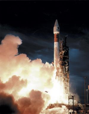 |
| A Lockheed Martin Atlas rocket launches a communications satellite for Inmarsal from Cape Canaveral Air Force Station. |
The propulsion systems for our nation's satellites and launch vehicles, as with every component manufactured for the NASA's Space Program, must meet high quality certification standards. This means that every weld must pass the highest purity and integrity tests.
Lockheed Martin Space Systems Company—Astronautics Operations in Denver focuses primarily on manufacturing launch vehicles like the Atlas and Titan rockets and fabricating spacecraft for NASA and Jet Propulsion Labs (JPL). These are deep-space spacecraft for different planetary and celestial explorations, such as the current Cassini mission to Saturn and the Genesis mission to collect particles of solar wind.
This facility designs, fabricates, and tests propellant tanks, feed line tubing, and control systems used to propel a launch vehicle or spacecraft to the proper orbit. Individual components of the core vehicles that may be found in the plant include the fuel tanks, main engines, electrical harnessing, and black box control units. Systems integration and testing also are done.
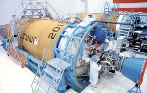 |
| Technicians at Lockheed Martin Space Systems Company - Astronautics Operations assemble the first single-engine Centaur upper-stage rocket in a clean room. Centaur upper-stages fly atop Atlas rocket boosters. |
For a typical spacecraft, the propulsion system's tubing requires more than 300 welds. The spacecraft and launch vehicles use a variety of tubing, mainly made of stainless steel and titanium materials, with wall thicknesses varying from as thin as 0.0016 to 0.090 inch and diameters ranging from ⅛ to 1-½ inches.
Because some of the material used for the tubing is thin and thus is difficult to weld consistently by hand, the facility uses automatic orbital welding. This process helps to make consistently uniform welds.
The products must be defect-free, so the welds must have full penetration and meet Class A X-ray quality standards. Much time and effort are expended on process control to ensure that every weld meets the rigid quality standards. The orbital weld heads do not contaminate the tube, which can cause an internal system leakage problem or a weld defect such as porosity. The purge gas is maintained clean and free of oxygen or moisture contamination from the supply tank to the weld joint.
The weld head maintains part alignment and provides complete inert gas coverage of the weld zone. The orbital welding power supply maintains control over critical welding parameters such as amps, volts, and travel speed, which are necessary for successful welds.
For this type of welding, the equipment used must have good arc-starting control. In addition, it shouldn't deliver welding current unless an arc is established. This helps to prevent burn-through on the thin materials being welded.
The facility uses closed-chamber welding heads manufactured for orbital welding in the aerospace and other high-purity industries. These heads are designed specifically for the autogenous welding of the thin stainless steel and titanium tubing. The protective gas covering made possible by the closed welding head prevents discoloration and embrittlement caused by exposure to oxygen, nitrogen, or hydrogen, all of which are detrimental to the welds.
Tubing subassemblies are welded on the bench in a tooling fixture. In addition to tubes, the weldments consist of other components such as pyro (Squibb Taylor) valves, latch valves, pressure transducers, regulators, tube reducers, and flow orifices.
When these subassemblies are mounted onto the vehicles, the tubing is interconnected to the fuel tanks and then to the rocket engines. Orbital welding also is used to connect the subassemblies on the main structure. To do this, the welders bring the equipment to the vehicle and weld in position. The main weld joint is a square butt weld, and socket butt welds also are used.
There are instances, however, of close weld head access, such as when two elbow fittings are welded together or a tube is connected to a component inside the spacecraft structure.
The facility always tries to weld equal wall thicknesses, if possible. Occasionally, however, mismatched wall thicknesses are welded. This is not a preferred method of design, but it can be handled when necessary.
The facility has one application in which a lap fillet weld is made between two tubes with different outside diameters (ODs). A half head is used so that the welders need to clamp on only one side of the weld joint. When different sizes of tubing are welded, the weld head can be changed with little effort.
For example, if there is a setup for ¼-inch tube and the welder has to change to ⅜-inch tube, an extra weld head already is set up for ¾ inch. The second weld head is plugged in, the machine's settings are changed, and the welding is begun. The same power supply is used.
Having multiple weld heads available for different tube sizes can save setup time, but weld head inserts can be changed to accomplish the same thing.
The company has also found that although the orbital welding process is unique and requires knowledge of metallurgy, detail fit-up, proper part cleaning, and other basics, the time it takes to train someone for automatic welding is less than that for manual welding.
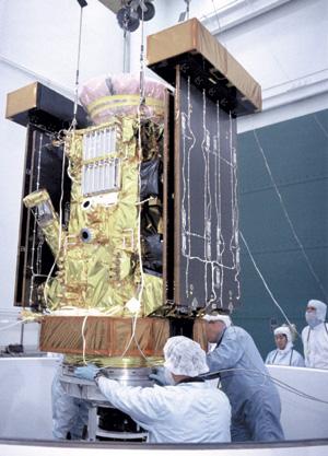 |
| Lockheed Martin Astronautics technicians prepare the Stardust spacecraft for a spin balance test. The spacecraft was designed and built for the JPL and NASA. |
Cleanliness is critical. Material is certified for chemistry, strength, and other criteria before it is accepted. The titanium and stainless steel tubing can have no contamination and must be totally clean. Using the engineering CAD data for proper configuration, the facility first bends the tubes to shape with NC bending equipment.
The tube ends are kept square to 0.002 inch and lightly deburred to ensure tight fit-up for welding. The tube then goes through a sequence of cleaning steps to bring it up to the facility's requirements.
All of the orbital welding is done in a clean room. The tubes go through a high-level cleaning process in which they are checked for particulate contamination and nonvolatile residue. The work is done in a Class 10,000 or Class 100,000 clean room, depending on program requirements.
Maintaining this cleanliness level requires a controlled-access room with special air filtration, and the welding technicians must wear full clean-room suits, including latex gloves. Also, detailed procedures are in place for handling the hardware to ensure that no contamination is introduced during the welding process.
The welders then fit the tube for welding, ensuring that no gap or mismatch is present at the weld joint. The parts are given a final solvent wipe and visual check before being assembled and welded.
The Astronautics Operation is responsible for delivering a certified propulsion system to NASA, which then uses all the test data that the company generated for NASA's acceptance of weld quality and system functionality.
Weld procedures are fully qualified through Lockheed's quality control lab before welding is performed on a vehicle. Once the vehicle is welded, the welds are inspected visually, X-rayed, proof-tested, and helium leak-tested at least once. Sometimes the propulsion system goes through several cycles or different cycles of inspection to ensure system integrity.
During certification, X-ray occasionally finds a lack of penetration indication. This type of defect occurs if the tungsten electrode isn't aligned perfectly over the weld joint. A small portion of the weld might not have been fully penetrated. Typically, a repair reweld cycle is made over that weld. Argon gas is used to ensure that the welder has a good purge before any welding or rewelding is done.
Getting ready to reweld can be a challenge and requires the same setup as for the original weld. A preproduction test sample is hooked up inline with the system being welded. This allows welders to test the welds before the weldments ever go onto the vehicle. The same purge setup used for welding also is used for testing. This avoids having to break the purge and wondering if the purge was restored to its required level.
Welds on space-bound products are critical. Once a vehicle is launched and in orbit, there is no way to fix it. If just one weld fails, a mission can be lost, with catastrophic consequences.
Welding applications in the aerospace industries demand high precision, a quality that can be entirely reproduced, and a reject rate that is as low as possible. Automatic orbital welding is being used to help to meet these requirements.

The Tube and Pipe Journal became the first magazine dedicated to serving the metal tube and pipe industry in 1990. Today, it remains the only North American publication devoted to this industry, and it has become the most trusted source of information for tube and pipe professionals.
start your free subscription
Easily access valuable industry resources now with full access to the digital edition of The Fabricator.

Easily access valuable industry resources now with full access to the digital edition of The Welder.

Easily access valuable industry resources now with full access to the digital edition of The Tube and Pipe Journal.

Easily access valuable industry resources now with full access to the digital edition of The Fabricator en Español.
In this episode of The Fabricator Podcast, Caleb Chamberlain, co-founder and CEO of OSH Cut, discusses his company’s...


