


Technical Sales Manager
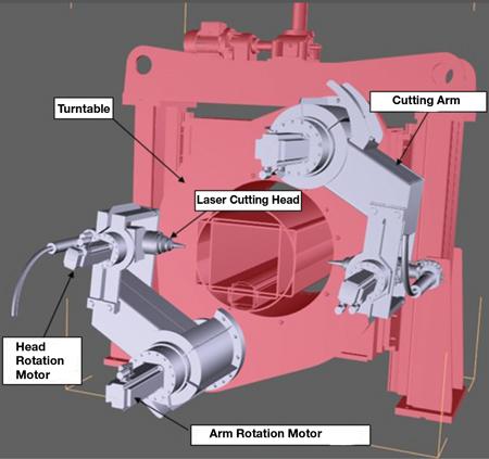
Because an Nd:YAG laser uses fiber-optic cables to direct the laser beam to the workpiece, it can be programmed for cutting a variety of shapes.
Manufacturing tube or pipe is full of challenges—procuring good-quality raw material, maintaining the tooling, setting up and aligning the mill, and so on—and when everything is dialed in and the mill is putting out good product, the next challenge is increasing the throughput. Typical mill speeds these days are much higher than they were decades ago, and they’ll only increase as technologies improve.
Like any mechanical system, a mill can run only as fast as its slowest component. Understanding the advantages and disadvantages of various cutoff systems is the first step in making sure the cutoff keeps up with the rest of the mill.
Dimple-free shears use two actions. The first cuts round tube at the 12:00 o’clock position, near the weld bead; the second shears the tube. For square and rectangular tube, the shear is inclined 45 degrees and scarfing is not used. Depending on the wall thickness and workpiece material, the process can require as little as 350 milliseconds. Because it’s a fast process that produces dimple-free cuts, this sort of shear works well on high-speed mills, even when making short cuts, and it produces finished parts that need no further processing (offline cutting).
The key to an electrically powered shear is the flywheel’s speed; it has to rotate fast enough to provide enough energy to make the cut. When the device actuates, two jaws clamp the tube, the first tool clips the weld bead (the top, where the blade enters) and the second tool cuts the workpiece.
A typical application is furniture tubing. On a line running 1,180 feet per minute (360 meters per minute), a shear can cut 20-ft. (6-m) lengths at a production rate of one piece per second. However, the fastest speed isn’t always the ideal speed. In this situation, which was an actual application, the ceramic inserts of the outside scarfing unit didn’t last long, even when three stations were used. To extend the life of the inserts, the speed was reduced to 820 FPM (250 MPM). This speed was found to have the optimal productivity—a reasonably fast line speed with infrequent line stops to replace the scarfing unit inserts.
As the name implies, the friction saw uses heat developed by friction to cut the tube, pipe, or profile coming off the mill. Friction saw blades normally are manufactured from two materials: chrome-vanadium steel (80CrV2 or 1.2235) and tungsten-molybdenum (73WCrMoV2 or 1.2604).
The mechanical properties of these materials are nearly constant over the expected range of operating temperatures, and they can withstand thermal shocks. They also are immune to vibrations and resonance phenomena. They normally are used for cutting carbon steels in hardness from 45,000 to 90,000 PSI. Friction saw blades can be toothless, V-notched, milled square, or prepared with a variety of notches.
The speed at the blade’s periphery is high, often 260 to 360 ft. per second. Depending on the material to be cut, the feed approaches 200 inches per minute.
Blades are heat-treated to reach a surface hardness in the range of 45 to 55 HRC. Using blades with hardness in the low end of the range (45 to 48 HRC) is advantageous because they have more toughness and therefore can stand up to minor impacts without much risk of cracking. Blades at the high end of the hardness range (52 to 55 HRC) aren’t as tough, but the cutting edges remain sharper for longer periods of time.
Friction raises the temperature in the cutting area, focusing the heat at the tips of the blade teeth. The saw blade rim does not reach the same high temperature of the material because it engages the material only in the cutting zone and it is cooled immediately during the remaining arc of rotation by the surrounding air and by coolant.
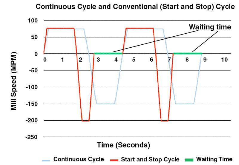
A conventional flying cutoff start and stop cycle moves the carriage using maximum acceleration to reach production speed, synchronizes with the mill speed for the cut, then decelerates and comes back at maximum speed, stops, and waits for the next cycle (red line). A continuous cycle does not stop and wait; it uses all the time available, thus reducing acceleration and reverse speed, depending on cycle parameters (blue line). In some cases the two cycles are equal; in all the other cases, continuous cycle reduces the mechanical stresses on the equipment. The reduction can be substantial.
The friction process relies on three factors to make the cut:
These factors work together to provide a continuous, progressive heating of the cutting zone, resulting in the cut—a series of small chips removed from the tube or pipe.
The main advantage is the low cutting time and the high production speeds achievable; another is that a friction saw can cut an internal bead without affecting blade life. However, they do have a number of drawbacks:
Coolant. Friction saws need a spray system to cool and lubricate the blade. Lubrication reduces heat on the blade faces and, combined with the cooling effect of the emulsion, maintains the temperature of the blade within operating limits. It reduces the tendency for chips to stick to the saw’s surfaces and optimizes the cutting process. The result is longer blade life and longer intervals between sharpening.
However, too much coolant can be counterproductive. The localized cooling reduces the temperatures in the cutting zone. The right amount of coolant strikes a balance between chip removal and cooling effect.
Variable Feed Rate. Single-speed friction saws are the norm, but modern components, such as servo valves and linear transducers, enable speed changes during the cutting process.
As the blade wears through normal use and repeated sharpenings, its diameter decreases. On saws that have one speed, the cutting speed (the blade speed at the periphery) decreases as the blade diameter decreases. The ability to vary the saw’s drive speed allows the operator to maintain the optimal cutting speed regardless of the blade’s diameter.
Precise control of the blade’s peripheral speed and the feed rate allows operators to make cleaner cuts with drastic reduction of burrs or deformations of the tube.
Although a cold saw isn’t nearly as fast as a friction saw, the result is a clean cut that doesn’t need deburring. Eliminating the deburring step means that the two processes are roughly comparable in throughput. When chamfering is required, the chamfering tool lasts longer when used on a burr-free edge. Also, because the cut temperature is extremely low compared to friction sawing, the material doesn’t need to be quenched, so it doesn’t suffer from the quenching effect.
The high-speed steels (HSS) used in making cold saw blades, and the surface treatments used on them, are improving continuously, which extends the blade’s service life and reduces cutting time.
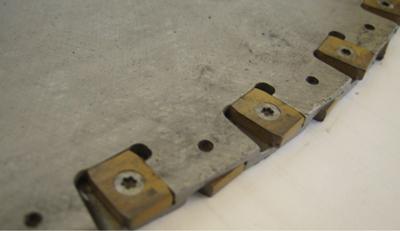
Teeth attached to both sides of this saw blade enable it to perform in the most demanding applications, cutting very hard materials, thick-walled workpieces, and the internal weld bead. The drawback to cutting the weld bead is reduced blade life.
A cold saw can keep up with a mill producing small-diameter carbon steel tube running at 650 FPM (198 MPM) making 20-ft. (6-m) cut lengths.
Tungsten carbide-tipped (TCT) blades are used to cut heavy-gauge material (more than 0.25 in. [6 mm] and high-strength alloys (yield strength up to 145 KPSl [1,000 MPa]). They also work on thin-walled tube. Choosing HSS or TCT on thin-walled tube depends on factors such as material hardness, production speed, and operator skill.
Single cold saw blades are used on tube and pipe diameters up to 5 in. (127 mm) or so. For sizes larger than this, a twin cutoff system is advantageous, which uses two blades for fast cuts. This sort of system has smaller blades than a single-blade system and can be programmed so that the blades work simultaneously or alternately. The software performs the necessary calculations to determine the cutting paths, maximizing the cutting rate, minimizing overlap, and preventing collisions.
Orbital cutting systems are suitable for tube and pipe diameters larger than 8 in. (219 mm). Two- and four-blade models are available, and they can be programmed for round, square, and rectangular shapes.
Because cold saw blades are available in two varieties, HSS or TCT, and because HSS blades can be enhanced with various coatings, such as titanium nitride (TiN), titanium carbo-nitride (TiCN), and titanium aluminum nitride (TiAlN), it takes an experienced saw operator to choose the best blade for the application and determine the saw speed and feed rate.
As the workforce ages and retires, this valuable knowledge exits the workplace. To help less knowledgeable workers, the role of software is becoming more critical in cold saw control. For a flying cutoff on a tube mill, a cold saw is only as good as the software.
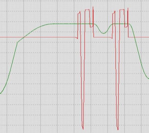
Cold Saw Carriages. A conventional flying cutting carriage system accelerates the cold saw to match the tube’s speed, maintains that speed during the cutting process, then decelerates quickly to a stop. It then reverses direction, accelerates as quickly as possible, achieves full speed, and returns to its home position where it waits for the next cut. The severe accelerations and decelerations, followed by abrupt stops and direction changes, subject the drive system components to substantial mechanical stress.
Another mode, called continuous cycle, matches the carriage’s motions closely to the application. It uses a motion profile that eliminates the wait time between cuts. Rather than waste time between cuts, it uses this extra time for the carriage’s motion, thereby minimizing the accelerations, decelerations, and top speed of the carriage. This reduces the stresses on the drive system.
Another development in mill cutoff systems is the laser. The advantages are fast, burr-free cuts made on many workpiece sizes without the need for a tool change. A CO2 laser, which uses mirrors to direct the laser beam, handles round shapes only. An Nd:YAG laser, which uses fiber-optic cables to guide the light to the cutting area, is easier to maneuver (see Lead Image). The Nd:YAG laser has a turntable that rotates the two cutting heads around the workpiece, which are always perpendicular to the profile to be cut.
Unlike roll formed profiles, tube and pipe often contain a weld bead (scarf) that must be cut. The internal weld bead is sliced off of the tube or pipe’s ID by a scarfing tool. The result of the process is a long, sharp strand of metal loose inside the tube that presents a hazard. A friction saw can cut it, as can a specially developed TCTS blade with acceptable results in duration depending on bead dimensions.
The cutoff unit uses the standard cutting parameters during most of the production run and makes a double cut when necessary.
However, because scarfed weld bead isn’t in a fixed position, it tends to damage most cold saw blades. Likewise, on large-diameter tubes, twin or orbital units just cut through the wall (not the entire tube), and do not cut the weld bead. In such cases, the cutoff unit cuts the tube or pipe to the correct length, but the weld bead continues to grow.
An ID bead cutter works by adjusting the roll speed to drive the two ends of the tube (head and tail) to the correct position for cutting and minimizing the protruding part of the internal bead from the surface of the tube, preventing subsequent problems for the finishing section.
Testing a short length of tube to verify its integrity is a common requirement. Usually the mill operator programs the cutoff system to cut a tube longer than necessary. The excess tube, the test sample, is cut off in an offline cutting operation. However, tube and pipe producers have another choice, a flying test cut.
Instead of the normal, once per carriage cycle, this process makes two cuts in one cycle. One of the cuts results in a standard-length tube, which continues down the mill to the next station. The other cut results in a short tube that gets evacuated laterally.


The Tube and Pipe Journal became the first magazine dedicated to serving the metal tube and pipe industry in 1990. Today, it remains the only North American publication devoted to this industry, and it has become the most trusted source of information for tube and pipe professionals.
start your free subscription
Easily access valuable industry resources now with full access to the digital edition of The Fabricator.

Easily access valuable industry resources now with full access to the digital edition of The Welder.

Easily access valuable industry resources now with full access to the digital edition of The Tube and Pipe Journal.

Easily access valuable industry resources now with full access to the digital edition of The Fabricator en Español.
In this episode of The Fabricator Podcast, Caleb Chamberlain, co-founder and CEO of OSH Cut, discusses his company’s...


