


Undergraduate Intern
For drawing tube or pipe, a lubricant must be able to withstand extreme pressures and significant heat buildup. A lubricant without these characteristics can lead to ID scratches and a draw force that increases rapidly. In extreme cases, the wall fails.
Testing and validating new lubricants is nothing new to the tube and pipe industry. These steps are necessary, especially when an existing lubricant is discontinued. The most recent lubricants targeted for replacement are chlorinated paraffins, which are used commonly in tube and pipe manufacturing mills around the world.
European and Canadian regulations regarding these lubricants have left tube and pipe manufacturers searching for equally effective, greener replacements. While many products are available, including lubricants removed by organic solvents or alkalines, no two are identical. It is the job of manufacturing personnel to determine the best replacement lubricant—the one that causes minimal process disruptions and maintains the product’s quality.
For heavy metal forming, chlorinated oils and sulfur-based alternatives are the industry standards. The heat and pressure generated from tube drawing are applied directly into the lubricant, causing chemical decomposition and increased fluidity. When chlorinated oils are used, the byproducts released from this reaction include carbon oxides; carbon dioxides; and gaseous hydrocarbons, including gaseous chlorinated hydrocarbons and hydrogen chloride gas. The main environmental focus of these lubricants is the release of chlorinated gases after disposal. Their sulfinated counterparts release sulfur dioxide and monoxide as well.
When testing new lubricants—in this case, for plug drawing—it’s critical to establish benchmarks relevant to the lubricant currently in use. Benchmarks include the cost of the lubricant; forming force; the cost of the cleaning agent and time needed to remove the lubricant; and product quality. Likewise it is critical to use one set of methods or practices for every test. For example, it is imperative to use a single lubricant application method, and to apply a consistent quantity of lubricant, for every trial.
Tip: When evaluating a new lubricant, it’s critical to use the actual manufacturing conditions—the same equipment and process. It might be a challenge to schedule time for lubricant tests on production equipment, but it provides the best results. Running initial tests in a lab, or on nonproduction equipment, can provide a good start, but doing final tests in a production setting provides the most accurate results.
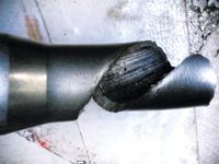
Four chloride-free lubricants were chosen for evaluation. A chlorinated lubricant was included in the test to provide a baseline, or reference. Before the lubricants were evaluated on production benches, preliminary tests were conducted on a sample bench (see Figure 1). In the primary test, a stainless steel tube with 0.500-inch OD and 0.065-in. wall thickness was reduced by plug drawing. The bench was equipped with a load cell, allowing a view of the draw force as it changed during the draw. After they were drawn, the tubes were inspected for OD and ID scratches. Failures varied from slight to drastic (Figure 2), but regardless of severity, any scratch was reason to discontinue testing that particular lubricant. Draw load data eliminated two of the four nonchlorinated lubricants.
After the laboratory testing was complete, the successful lubricants were tested on the production floor. The second test reduction took place on a full-size draw bench using two tubes. The first was an INCONEL® alloy 625 tube, 1 in. OD, 0.070-in. wall thickness; the second was a stainless steel tube slightly larger than the original 0.500-in.-OD tube. Both draws reduced the tube approximately 30 percent.
This bench was not equipped with a load cell, so evaluation was based solely on surface quality. As in the first test, a reference lubricant was used. The die and plug were cleaned in preparation for the new lubricant, which was applied in the same manner as the reference lubricant. Both nonchlorinated lubricants were successful in this second round of testing.
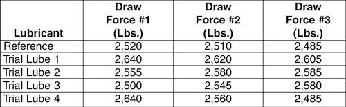
Comparing Draw Forces. The draw force was measured at three points during each pull. The draw force for the reference lubricant slowly declined as the lubricant’s viscosity decreased from the heat and pressure (see Figure 3).
Trial lubricant 1 showed a higher draw force than the reference lubricant yet a similar decline as the draw continued. Note that a higher draw force is not a reason to discontinue testing the lubricant; trial lubricant 1 was deemed successful because the quality was acceptable. It had no scratches and the dimensions were within the customer’s tolerances.
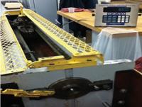
Figure 1: A test bench with a load cell provided initial draw force data for evaluating four trial lubricants. This step eliminated two of the four lubricants.
For trial lubricant 2, the draw force was basically equivalent to the standard during the first few feet of the draw. The sudden increase in draw force was empirical evidence that the lubricant was decomposing and thinning or a scratch had formed and was growing. Further trials and investigations revealed that trial lubricants 2 and 3 occasionally did result in scratched tubes, a quality failure that eliminated them as candidates. Trial lubricants 1 and 4 did not result in any quality issues, so they were tested further.
Tip: A draw force increase is not a reason to eliminate a lubricant. Check the tube for ID scratches and other quality issues; also check the plug for any pickup.
Removing the Lubricants. While anything can be cleaned with the appropriate chemicals, one of the criteria of the evaluation was to find a lubricant that disrupted existing manufacturing processes as little as possible. To evaluate ease of removal, a 6-in. length of tube drawn with the reference lubricant was placed into a 13.5-oz. bath of solvent. The tube sat undisturbed for 5 minutes; it was swirled in the bath for a few seconds, removed, then placed back into the bath for an additional 5 minutes. The 5-min. duration was selected to match the cleaning time needed for the reference lubricant.
When the tube seemed clean, it was removed from the solution. The time needed to remove the lubricant was recorded, and the test was repeated with samples drawn with trial lubricants 1 and 4. Then the solvent was removed.
Tip: Do not remove the cleaning liquid with anything that can remove the lubricant also. For example, if the cleaning bath is a solvent, use high-pressure air to evaporate the liquid. If the bath is alkaline, rinse the tube in cold water.
A simple tactile test—running a fingertip over the standard tube and the trial tube—was used to determine if the tube was clean enough for the next step.
Tip: If oil remains on the surface, repeat the cleaning process.
After the tactile test, scanning electron microscopy (SEM) and energy-dispersive X-ray spectroscopy, two of the most advanced methods to determine a metal’s cleanness, were used to evaluate the tube’s surface (see Figure 4 and Figure 5).
The atomic data from Figure 5 is from the center of Figure 4 (not the crystalline contamination near the top right corner). This shows high levels of carbon, which can be attributed to high carbonate levels in the drawing lubricant tested. This contamination existed only on the surface and could be removed with a light sandblast or pickling step.
Evaluating Surface Roughness. The tubing’s surface condition must also be factored into the lubricant choice. One way of testing this variable is a mechanical stylus profiler. Using a diamond tip with a radius of less than 0.0004 in. and a 90-degree angle, this machine was used to read the variation in wall smoothness along the tube’s OD and ID.
Figure 2: Some lubricants aren’t suitable for severe forming applications such as plug drawing. In this case, the lubricant didn’t provide sufficient lubricity to prevent a catastrophic failure.
After it was determined that neither trial lubricant 1 or 4 would affect the postdraw process, they were used in the production environment for validation. Both lubricants were used to draw several lots of tubes in a variety of sizes and alloys.
One of the nonchlorinated lubricants produced slightly scratched tubing during a heavier reduction; at this point, that lubricant was eliminated from validation testing. The other lubricant had no recorded issues during any reductions and was integrated into the drawing process.

The Tube and Pipe Journal became the first magazine dedicated to serving the metal tube and pipe industry in 1990. Today, it remains the only North American publication devoted to this industry, and it has become the most trusted source of information for tube and pipe professionals.
start your free subscription
Easily access valuable industry resources now with full access to the digital edition of The Fabricator.

Easily access valuable industry resources now with full access to the digital edition of The Welder.

Easily access valuable industry resources now with full access to the digital edition of The Tube and Pipe Journal.

Easily access valuable industry resources now with full access to the digital edition of The Fabricator en Español.
In this episode of The Fabricator Podcast, Caleb Chamberlain, co-founder and CEO of OSH Cut, discusses his company’s...


