


Contributing Writer
Editor's Note: Baicheng Wen is no longer with Roll-Kraft. This article originally appeared in the December 1999 edition of TPJ-The Tube & Pipe Journal.
 |
Two of the goals all manufacturing companies share are minimizing production costs and maximizing profits. In the tube and pipe industry, this can be accomplished by selecting the correct style of tooling.
Three basic styles of tooling are used to make tube and pipe:
1. Solid
2. Split
3. Carbide-inserted
The total cost—initial, rework, and lifetime—as well as the useful production life for the three styles, varies greatly. This article examines these differences, including the cost-effectiveness of mill setup, to help tube and pipe manufacturers select the most profitable tooling for their respective operations.
Solid Rolls. Solid rolls are the most common tooling used to make tube and pipe. This one-piece design has the lowest initial cost of the three styles of tooling because of its simplicity in construction.
Solid rolls are preferred in many applications for several reasons. In addition to the initial cost factor, solid rolls with small root diameters are designed to produce high driving forces to maximize mill efficiency. Second, physical limitations of the mills—such as vertical center distance, roll space, and bottom line—may require that smaller solid rolls be used. Third, solid rolls provide a cost-effective option for limited production runs.
Solid rolls often have to be reworked, which causes downtime and additional costs associated with mill readjustment. For example, reworking a set of solid rolls reduces the root diameter of the tooling. If these rolls are in the breakdown section, the forming line of the mill is lowered, which requires mill adjustment to raise the bottom drive shaft before production can resume. Shims are required on mills with limited or nonvertical adjustment capabilities, or side roll stands must be adjusted.
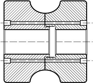 |
| Figure 1: Split rolls have wider flanges than solid tooling and require more space on the mill. |
In addition, reworked solid rolls have a lower surface speed, reducing forming speed if the drive speed on the mill is nonadjustable. Reworking solid rolls in one section of the mill might require reworking the entire set regardless of condition or need to maintain a correct forming line or mill speed.
Split Rolls. A split roll is a two-piece component bolted together to form a solid roll. A roll of this design is physically larger—wider flanges require more roll space on the mill—than a conventional solid roll used to produce the same size tube or pipe (see Figure 1).
When a split roll is reworked, the roll width is reduced to maintain the original root diameter and contour. As a result, mill setup is unaffected, mill speed and production rates should not change, and downtime is reduced. The only alteration required for the mill is the addition of spacers to each reworked split roll to compensate for the reduction in roll width. Because the reworked split rolls do not affect production parameters, only those rolls that are worn require rework.
Split rolls cost more, especially for lower-volume work. Both initial and rework costs exceed those of solid rolls. However, split rolls can be reworked more times than conventional rolls.
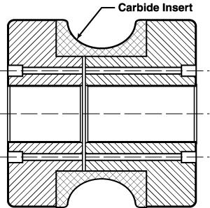 |
| Figure 2: Carbide tooling inserts fit inside the contour, or work area, of the roll tooling. |
Carbide-Inserted Rolls. A carbide roll is a steel split roll with a carbide insert in the work area, or contour, of the roll (see Figure 2). Because of the inserts' cost, this design has the highest initial cost of the three roll designs discussed in this article.
Life expectancy of these rolls is several times longer than that of other types made from D-2 tool steel, depending on the material being processed. In addition, carbide rolls keep working with their original contour over the life of the tool. Carbide rolls can maintain tight production tolerances for a long period of time as well. The coefficient of friction of carbide inserts is less than that of steel.
For a specific forming operation, manufacturers need to gather as much information as possible to select the proper tooling.
The first step in the tooling selection process is gathering all mill specifications, including the mill layout. Specifications such as the number of drive motors, roll space available on the drive shaft, distance between the driven and idle stands, and minimum and maximum vertical centerline distances on the respective mills play an important role in whether a particular tooling design works for a specific tube size.
For example, a line with a single motor drive is a prime candidate for split and bolted tooling as long as the driven roll space has enough room for the tube diameter and the increased flange width typical of a split roll. This is a normal consideration when trying to produce the maximum diameter possible on a particular tube mill.
Second, the tube company should define and verify the material that will be formed and the mechanical properties of that material.
The amount of work done at each pass and the contour clearance are different for low-carbon steel, stainless steel, and aluminum. Using the same set of tooling to form these three different materials undoubtedly will produce disappointing results. Even within the definition of low-carbon steel, the yield and tensile strengths and elongation rate vary based on alloying elements and rolling practices. If manufacturers are aware of these factors up front, they will be better able to choose a superior roll design for the individual application.
Anticipated production volume is important to consider beforehand as well. Rolling 1 million feet per month of a hot-rolled pickled and oiled (HRP&O) product may be fine on a solid set of D-2 tooling. But if the material is hot-rolled black, the wear factor may dictate use of carbide-inserted rolls to achieve a better return on investment (ROI) over using multiple sets of D-2 with the associated reconditioning costs. If the product begins with a projected low initial volume, it may be better to use D-2 until volume increases require longer production runs, which may require carbide tooling to maintain quality requirements.
Finally, manufacturers must calculate the projected tooling costs for each type of tooling to choose the lowest-cost tooling for that particular production run, based on total cost of regrinding and replacing the tooling over a certain period of time.
Tube and pipe manufacturers also should consult with their tooling suppliers to answer specific questions about their particular forming operations. Technical assistance from suppliers on cost comparisons and tooling performance is invaluable in the selection process.

The Tube and Pipe Journal became the first magazine dedicated to serving the metal tube and pipe industry in 1990. Today, it remains the only North American publication devoted to this industry, and it has become the most trusted source of information for tube and pipe professionals.
start your free subscription
Easily access valuable industry resources now with full access to the digital edition of The Fabricator.

Easily access valuable industry resources now with full access to the digital edition of The Welder.

Easily access valuable industry resources now with full access to the digital edition of The Tube and Pipe Journal.

Easily access valuable industry resources now with full access to the digital edition of The Fabricator en Español.
In this episode of The Fabricator Podcast, Caleb Chamberlain, co-founder and CEO of OSH Cut, discusses his company’s...


