


Minimizing scrap on laser welding mills
Systems monitor parameters before, during, after welding
Since the U.S. Patent Office awarded the first patent for a laser in 1960, this technology has proven useful for dozens of applications, including medical, communication, military, law enforcement, communication, and, of course, industrial. The laser’s energy density makes it ideal for applications that need a highly concentrated light source, but the same principle, when energized by a powerful energy source, generates enough heat to cut metal. It also works well for welding.
The fundamental difference between cutting and welding with a laser concerns aiming accuracy. When used for cutting, a beam that strays from its intended cutting path still makes a cut. However, this doesn’t work for welding. Because the laser beam is small compared to traditional sources of weld heat, a beam that misses the weld seam doesn’t make a good weld. Aiming accuracy is a much bigger challenge when the weld seam moves, as it often does on a tube or pipe as it moves through the weld box on a mill.
However, challenging doesn’t mean impossible. Laser welding on tube and pipe mills is possible because all of the laser-related equipment works together, and as electronic components advance, these systems provide for more reliable welds.
The history of two TRUMPF products, SeamLine and SeamLine Pro, tells how this technology has improved over the decades.
Mechanical to Electronic
The company’s first laser-guiding system was a simple mechanical setup. It used a pressure wheel, a steel disc that sat in the V—where the weld seam forms—and was connected to the laser head. As the weld seam shifted slightly left and right, the steel disc shifted with it, guiding the laser head and keeping the laser beam aligned with the weld seam. This system was state-of-the-art in the 1990s, but as industrial cameras and the related software became more sophisticated and affordable, accurate vision systems emerged. By the early 2000s, CCD cameras would facilitate the development of the SeamLine system, an electronic guidance system with the primary function of tracking the weld seam and keeping the laser beam centered on it (see Figure 1).
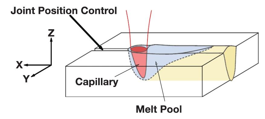
“It uses two light sources to illuminate the weld seam,” said Bill Weston, regional sales manager, tube and pipe key account manager for TRUMPF. “The light sources help it detect the weld joint position, measure the vertical offset of the edges, and measure the gap width,” he said (see Figure 2).
Mill operators everywhere would rather shut the mill down than make scrap, but more importantly they’d rather take remedial actions—making small adjustments on-the-fly—to prevent a mill shutdown. The SeamLine system tracks these parameters, and the operator programs it with preset limits, to provide both capabilities. The alerts call the operator’s attention to the mill to do some troubleshooting, and he has the option to shut the mill down if the parameters get too far from optimal.
A Decade of Improvement
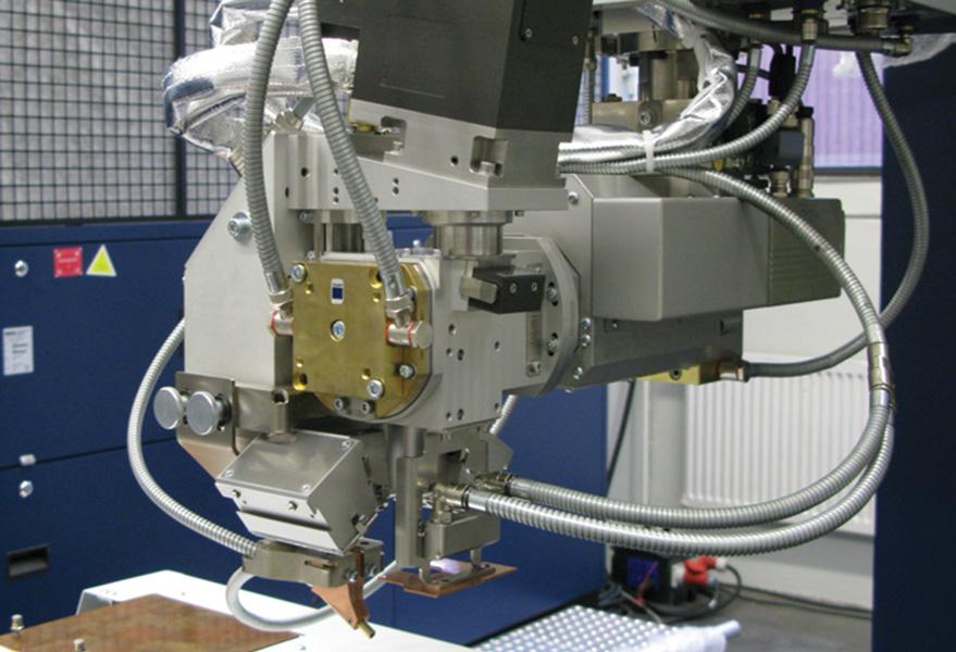
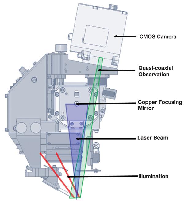
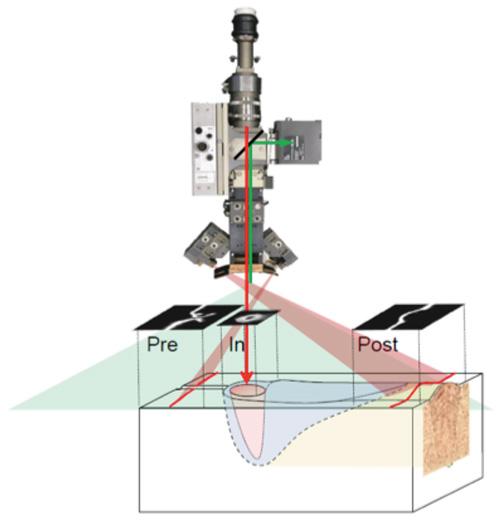
The company rolled out SeamLine Pro approximately 10 years after it introduced the original system. It has all of the capabilities of the first-generation control. In addition to tracking the weld seam in the preweld area, it monitors the weld pool and the postweld area (see Figure 3 and Figure 4). It uses external lighting sources and a single camera outfitted with three sensor systems to monitor these three areas.
One of the basic differences between the systems is the distance between the camera’s image processing area (pre-process) and the laser’s focus point (in-process). The original model’s sensor is 60 mm in front of the laser spot, whereas the latest model’s sensor is 2 mm away. Because one camera records both the joint gap and the focal spot, the system regulates the welding optics so that the focal spot is positioned directly above the joint gap, which eliminates adjustment error between the two points.
“In addition, there have been many advances in electronic technology during the last few years,” said Greg LaManna, project manager—high power lasers for TRUMPF Inc. The latest system uses a CMOS camera, related electronic hardware, and corresponding software to achieve a much higher sampling rate. The original system has a measurement rate of 50 images per second (50 Hz). At 300 Hz, the new control provides six times as much information in the same timeframe. The effect of these enhancements is a 30-fold improvement in positioning accuracy, according to sources. They also reduce the amount of time and material needed when changing the mill setup from one product to another, thereby increasing productivity and reducing associated downtime costs.
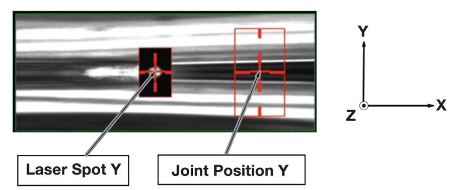
Figure 1
Adjusting the laser beam’s location to keep it centered on the
weld seam (joint) is the primary goal of a laser-guiding system.
Weld quality monitoring with the postprocess sensor is the third function of the latest system. It uses a visual system to measure the weld bead height and can determine the degree of underfill or overfill. It also monitors the postweld seam width.
Both systems allow the operator to define specific warning and intervention limits of measured attributes, such as gap width, edge mismatch, and the seam’s Y-axis position. The alerts are intended to give the operator enough time to intervene to make the necessary changes to continue to make viable product.
Not a Replacement
While the new weld control offers a number of additional features, the company has no plans to discontinue the original. It’s still viable for many applications today.
“It’s a matter of the finished product’s value,” Weston said. “For a company making straight lengths of tubing, the original system continues to be a very suitable system.”
“However, the latest system would be worth consideration for other applications requiring greater positioning accuracy,” LaManna said. “A 20- to 40-ft. length of tube with a bad weld is one thing. A 15,000-ft. coil with a bad weld is something else altogether.”
About the Author

About the Publication

subscribe now

The Tube and Pipe Journal became the first magazine dedicated to serving the metal tube and pipe industry in 1990. Today, it remains the only North American publication devoted to this industry, and it has become the most trusted source of information for tube and pipe professionals.
start your free subscription- Stay connected from anywhere

Easily access valuable industry resources now with full access to the digital edition of The Fabricator.

Easily access valuable industry resources now with full access to the digital edition of The Welder.

Easily access valuable industry resources now with full access to the digital edition of The Tube and Pipe Journal.

Easily access valuable industry resources now with full access to the digital edition of The Fabricator en Español.
- Podcasting

In this episode of The Fabricator Podcast, Caleb Chamberlain, co-founder and CEO of OSH Cut, discusses his company’s...
- Trending Articles
1
Zekelman Industries to invest $120 million in Arkansas expansion

2
3D laser tube cutting system available in 3, 4, or 5 kW

3
Corrosion-inhibiting coating can be peeled off after use

4
Brushless copper tubing cutter adjusts to ODs up to 2-1/8 in.

5
HGG Profiling Equipment names area sales manager
