


Marketing Manager
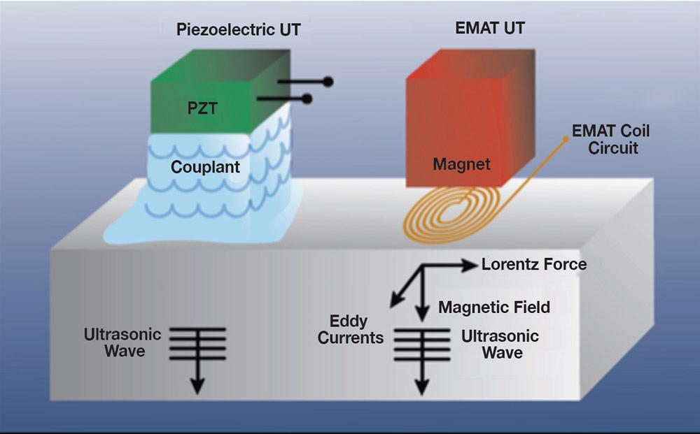
Figure 1
Although piezoelectric transducers and electromagnetic acoustic transducers do the
same thing, propagate an ultrasonic wound wave through the material under test,
they do it in different ways.
Nondestructive testing (NDT) plays two critical roles in welded tube and pipe production. First, tests conducted early in the production process can save the company time and money by detecting problems that may lead to poor weld quality. Second, when problems occur, immediate detection can prevent creating large amounts of scrap or substandard product.
The electric resistance welding (ERW) process isn’t perfect. Typical defects include entrapments (black penetrators), prearcs (white penetrators), lack of fusion (LOF), LOF at edges (puckers) or midwall, cast weld, porosity, stitching, hook cracks, and paste welds (cold welds). After welding, ID and OD trim (under- or overcut) can result in downgraded or scrapped product. Before welding, skelp entering the line can contain surface or internal defects, or can be out of specification for thickness.
Traditional techniques for ERW inspection use piezoelectric transducers. While highly efficient and versatile, piezoelectric transducers need to be coupled to the part under inspection with high pressure or a liquid medium. These can limit the scanning ability or produce interferences, respectively.
An alternative process, electromagnetic acoustic transducer (EMAT), is a more recent development that uses two interacting magnetic fields to generate ultrasonic sound waves in the part. A relatively high frequency (RF) field generated by electrical coils interacts with a low frequency or static field generated by magnets to generate a Lorentz force in a manner similar to that of an electric motor. This disturbance is transferred to the lattice of the material, producing an elastic wave. In a reciprocal process, the interaction of elastic waves in the presence of a magnetic field induces currents in the receiving EMAT coil circuit. For ferromagnetic conductors, magnetostriction produces additional stresses that enhance the signals to much higher levels than could be obtained by the Lorentz force alone. Various types of waves can be generated using various combinations of RF coils and magnets. See Figure 1.
Because the sound is generated in the part inspected instead of the transducer, EMAT has several characteristics that appeal to tube and pipe producers:
On small pipes, guided waves are ideal for ERW inspection. An EMAT transmitter can be located at 90 degrees, sending sound waves clockwise, with a receiver at 270 degrees to detect reflections from the weld. A second set of sensors with the transmitter at 270 degrees and receiver at 90 degrees sends sound counterclockwise to complement the first set. Guided waves fill the volume of the material, thereby enabling inspection of the entire weld in one shot for detection of hook cracks, zipper welds, lack of fusion, and mismatch with greater reliability than angled beams on small tubes. EMAT also can be complemented with eddy current technology for detection of point-type defects, and it permits up to 55 degrees of weld drift during inspection (see Figure 2).
On large-diameter pipes, welds can be inspected with EMAT immediately after the welding process, which minimizes waste. Inspection without couplant permits installation immediately after the welding head to detect all weld discontinuities, API standard defects (penetrators, LOF, cast weld, porosity, hook cracks, and stitching), and trimming defects (ID and OD). Trimming problems alone can account for much of the scrapped pipe because they are detected long after the problem begins.
Skelp inspection for planar defects is performed using arrays of sensors that generate normal beam 0-degree waves. The sensors can be placed across the entire width of the skelp or concentrated in the weld zones only. EMAT is much less sensitive to vibrations or sensor movement and can be used at very high speeds for screening of skelp. The same normal beam technique can be used for thickness measurement of the skelp with resolution of ± 0.0001 in. (2.5 µm).
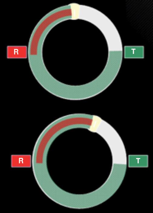
Figure 2
EMAT’s guided wave capability means that
the weld seam location doesn’t have to
be rock-steady. It can measure the weld’s
soundness despite the weld seam drifting
as much as 55 degrees.

The Tube and Pipe Journal became the first magazine dedicated to serving the metal tube and pipe industry in 1990. Today, it remains the only North American publication devoted to this industry, and it has become the most trusted source of information for tube and pipe professionals.
start your free subscription
Easily access valuable industry resources now with full access to the digital edition of The Fabricator.

Easily access valuable industry resources now with full access to the digital edition of The Welder.

Easily access valuable industry resources now with full access to the digital edition of The Tube and Pipe Journal.

Easily access valuable industry resources now with full access to the digital edition of The Fabricator en Español.
In this episode of The Fabricator Podcast, Caleb Chamberlain, co-founder and CEO of OSH Cut, discusses his company’s...


