


Vice President of Length and Speed Systems
Editor’s Note: This article is adapted from “Improving Cut Length Control, NDT Defect Tracking, Final Length Inspection and More With Laser Velocimeters,” presented by Peter Nawfel at Pipe & Tube Houston 2014, sponsored by the Tube & Pipe Association International® and the International Tube Association, Houston, Sept. 16-18, 2014.
Laser velocimeters have been used for processing steel and other metals since the early 1990s, initially used in cold rolling of steel and aluminum. Their use improved the accuracy in measuring strip speed during rolling to improve mass flow calculations for automatic gauge control. Measuring strip speed with a laser velocimeter relies on the laser’s capabilities to provide accurate, repeatable, and reliable measurements and, because it’s a noncontact method, it isn’t susceptible to roll slip or diameter change as the roll wears, which can contribute to unpredictable measurement errors over the long term. The result is that a greater percentage of the coil is rolled to the specified thickness, increasing the amount of yield for each coil.
As optical and electronic components have become more affordable, so too have the systems, which have expanded their use to many more applications than before. Many tube and pipe mills use this technology as footage counters for incoming coil lengths; length and speed measurement sensors for controlling cut-to-length systems; trackers for defect detection systems; and validators for length measurement systems.
Laser velocimeters are optical sensors that measure the velocity and length of material in motion as it passes the laser’s sensor. They use the Doppler effect to measure the material’s speed. Proposed by physicist Christian Doppler nearly 200 years ago, the Doppler effect states that waves emitted, reflected, or scattered from a moving object undergo an apparent shift in frequency. As with sound emanating from a moving vehicle, light waves also appear to compress, or increase in frequency, as the object moves toward the viewer. As the vehicle moves away, the sound waves appear to stretch, or decrease in frequency, as do light waves (see Figure 1). The frequency shift is proportional to the velocity.
Laser Doppler velocimeters (LDVs) are designed to measure the Doppler frequency shift as the laser light is scattered from the material’s surface. As a result, the LDV provides an output directly proportional to velocity of the material being measured. By integrating the velocity in real time, these systems also determine the accumulated length of material that has passed the laser’s sensor in real time.
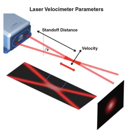
LDVs use the differential Doppler method to measure velocity. The laser beam from a single laser diode is split into two beams and directed so that they intersect at a fixed point in space (see Figure 2). This fixed focal point is called the standoff distance of the sensor system. As the beams intersect, they overlap in the area around the standoff distance, forming the measurement volume or depth of field of the sensor system. The sensor measures the length and velocity of material that passes within the limits of the depth of field. The output can be in any of several common formats, such as quadrature encoder pulse, RS-232, RS-422, Ethernet/IP, Profibus, and Profinet.
To Shift or Not to Shift. The two types of sensors are shifted and nonshifted. A nonshifted system splits the beam of a laser diode and redirects each beam to intersect at the standoff distance. In this case, the two beams exiting the sensor head have the same frequency. When the material is at a standstill (n=0), no modulation in intensity occurs. When the material begins moving, the Doppler effect causes one beam to take on a higher frequency and the other beam to take a lower frequency. The result is a modulation in intensity at the detector, the frequency of which corresponds to the velocity of the material.
The nonshifted system has a couple of limitations. First, because modulation does not occur when the material is at a standstill, the system doesn’t measure velocities near zero. Second, a nonshifted sensor detects any motion as an increase in modulation frequency. In other words, it interprets all motions, whether forward or reverse, as forward motion. Therefore, this type cannot be used in processes that stop and change direction.
The shifted system is more sophisticated. The sensor generates a reference frequency at material standstill (n=0) and compares it to the modulated frequency while the material is moving to measure the difference between the two. This allows the system to measure any speed, even no motion at all, and it can determine the material’s direction.
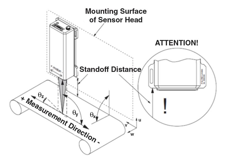
Installation and Alignment. Installation and alignment aren’t difficult, but they are critical for accurate readings (see Figure 3).
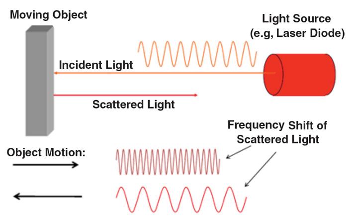
Figure 1
The light wave transmitted by the laser emitter has a known frequency. If that light is reflected from an object moving toward the laser receiver, the object’s motion causes an apparent compression in the frequency; if the object is moving away from the receiver, the frequency will appear to be stretched.
A stable passline yields the highest process accuracy and repeatability. However, many tube and pipe mills can run more than one diameter, so it’s not uncommon to have substantial changes in passline height. Resolving this is a matter of using a sensor with a depth of field large enough to handle the variations in passline height. Keep in mind that accuracy and repeatability are enhanced by keeping the ratio of passline variation to depth of field as small as possible.
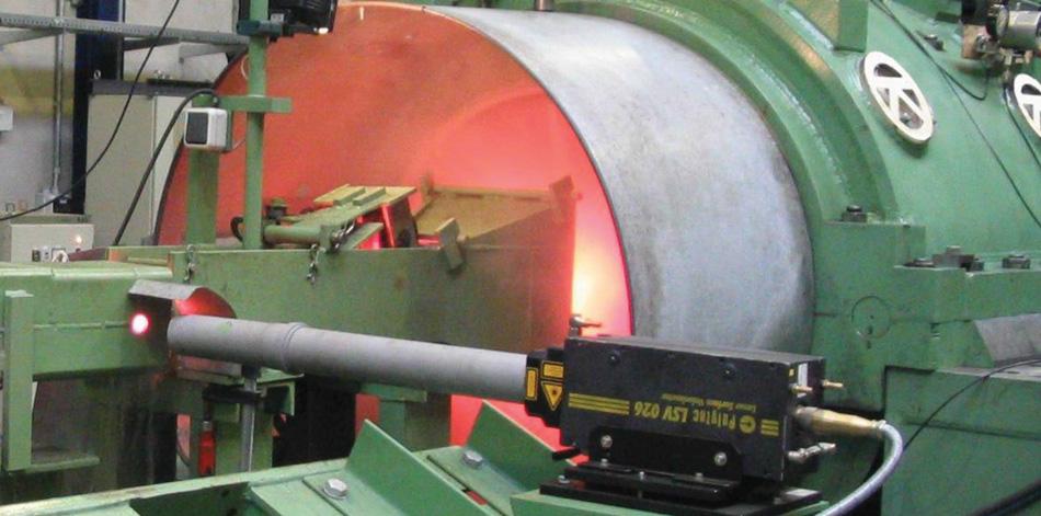
No Smoking, Please. LDVs don’t distinguish much between one surface or another—they operate just as well on hot, glowing surfaces as they do on cold surfaces. All they require for reliable measurement accuracy is a clear line of sight between the sensor and the surface to be measured. However, industrial environments aren’t always ideal. Optical systems often need assistance from auxiliary equipment to deal with smoke and airborne particulates.
For tube and pipe producers, the three main uses for LDVs are length measurements for cutoff, length verification, and defect tracking and marking.
Cut to Length. Improving cut length control repeatability and yield can be one of the most straightforward applications and provide the quickest ROI for laser velocimeters. They typically have an accuracy of ±0.05 percent and repeatability of ±0.02 percent. In many cases, tuning the process control loop can cut the tolerance by more than half, consistently delivering cut lengths that are in the range of ±0.02 percent. For length of 240 in., this results in a cut length tolerance in the range of ±0.0625 in. This is a very favorable tolerance considering that a mechanical system typically achieves a tolerance of ±0.125 in. for the same cut length.
Tube Length Verification. Whether making seamless or welded tube, it may be necessary to verify the precut length in the finishing area or at the weigh-measure-stencil stage. Either way, a noncontact system doesn’t need special provisions to engage at the leading edge of the product and disengage at the trailing edge.
Depending on required accuracy, two methods can be employed with laser velocimeters. The first is to use the internal material detection function, which triggers an internal length measurement to start at the leading edge of the pipe and stop it at the trailing edge. The final length then can be displayed for the operator or sent to a data acquisition or control system.
For those methods requiring greater optimization and tolerances of 0.05 percent or better, the laser velocimeter can be installed with two photo eye triggers, one on either side of the velocimeter. The purpose of the triggers is to optimize the accuracy of the edge detection at the leading and trailing ends of the pipe. Unlike velocimeters, photo eyes are designed specifically for this task. Although the velocimeter can identify an edge, the laser does not approach perpendicular to the surface and the laser spot can be up to 4 mm long, which has the potential to introduce some error into the measurement. Some photo eyes have very small spots for excellent spatial resolution coupled with high-speed triggering in the 200-microsecond range.
Defect Tracking and Marking. Nondestructive testing systems are designed to identify and mark an array of defects and pipe parameters including diameter, length, and wall thickness dimensions. Detectable weld defects include transverse and longitudinal, both on the OD and ID. After these defects are identified, the system marks the location for further action. Precise tracking of the defect position through the system and coordinating its position with the marking system is critical to proper quality control.
A fixed passline is the key to defect tracking accuracy. The velocimeter can be positioned on a drive block that moves up and down with the guide drivers to handle various pipe diameters. The velocimeter thus remains at a fixed standoff distance in relation to the pipe surface, regardless of pipe diameter.


The Tube and Pipe Journal became the first magazine dedicated to serving the metal tube and pipe industry in 1990. Today, it remains the only North American publication devoted to this industry, and it has become the most trusted source of information for tube and pipe professionals.
start your free subscription
Easily access valuable industry resources now with full access to the digital edition of The Fabricator.

Easily access valuable industry resources now with full access to the digital edition of The Welder.

Easily access valuable industry resources now with full access to the digital edition of The Tube and Pipe Journal.

Easily access valuable industry resources now with full access to the digital edition of The Fabricator en Español.
In this episode of The Fabricator Podcast, Caleb Chamberlain, co-founder and CEO of OSH Cut, discusses his company’s...


