


Ask the Expert: How can metal stampers achieve ever-tightening dimensional tolerance requirements?
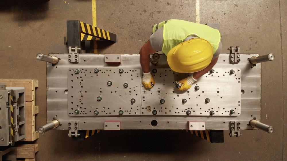
tunart / E+ / Getty Images
I have been working in the metal stamping industry for 40 years, designing tools for stampings from door hinges to medical device gears no bigger than 1/16 in. dia. Over the years, the customer-requested dimensional tolerances have consistently tightened up. What used to be +/-0.005 in. is now +/-0.002 in. and sometimes even as tight as +/-0.001 in. On top of that, they require capability. A CPK (capability index) of 1.33 essentially cuts your tolerance in half! How can we do this? It’s almost like customers expect the quality of machined parts for the price of a stamping.
I feel your pain. We at Micro are under the exact same pressures.
I can assure you that it is possible to stamp to these tight tolerances. Minimizing dimensional variation in your stampings depends on three big factors.
1. Robustness of the Tool Frame and Guide System
The tool frame or die shoe must be thick enough not to flex during stamping. A die shoe that flexes or bows at the bottom of the stroke provides no support under the tool right where the work is being done, and that causes dimensional problems. If you can move the ram up or down by 0.001 to 0.002 in. and change the part, you have proved my point.
We recommend using a 3-in.-thick die shoe when stamping 0.025-in. or thinner material, a 4-in.-thick die shoe when stamping 0.05-in. or thinner material, and so on. We have a few heavy rolling, coining, and extrusion dies running 0.080-in.-thick stock, and the die shoe is 6 in. thick.
The die stops also must be oversized to control the hit during every stamping cycle. Rather than use the typical 1-in.-dia. stops on each corner, we use 3- by 3-in. rectangular stops in six places when we can fit them. On the large tools in a 150-ton press, we use six to eight 3- by 5-in. stops. It takes a lot to stop a ram using that kind of tonnage.
Finally, maximize the number of guide pins and make sure they are robust. On a 2.5-ft.-long tool, use four guides, minimum 2 in. dia. On a 4-ft. tool, use four to six guides, minimum 2.5 in. dia. And on a 6-ft. tool, use six to eight guides, minimum 3.5 in. dia. Also be sure to use high-grade precision roller cages.
2. Design of the Lead Strip Piloting and Strip Progression Clamping in the Tool
This applies to the three-plate tool design. Make sure you have robust piloting and stripper clamping. Keep the strip level with lifters during forming. Use nitrogen cylinders and pressure pads to control the strip during forming. Calculate the forces needed to make the part and always use two to three times the force required in your pressure pad design to be safe. If you control the strip at every step as it progresses through the die, the result will be less variation in the output.
When you have pressure pads in the die chase, your stripper plate must overcome not only those forces but also the added force of the work being done. As with the pressure pad, design your stripper clamp for two to three times the force required.
3. Use of DFM for Each Tool
Use the design for manufacturability (DFM) process on every station in the die. As an example, if you have 0.0005-in. pilot clearance, then you can have 0.0005-in. total variation in your part dimensions.

Tolerance problems often start in poor design, such as weak part carrier tabs or a large part held to the die strip in a trimmed-out frame with many forms. The part naturally wants to pull into the forming operation. Even the slightest skidding will lead to variation. For this, you need to have several carrier tabs in both axes of the part.
Try adding pilot holes in the part, so when you are doing heavy forming, you can register the part accurately. We also commonly use stippled pressure pads. They feature a series of extremely fine, sharp diamond points that add a rough surface that helps eliminate skidding. CBN coat also adds roughness to a pressure pad surface.
Finally, try scoring the material before trimming to ensure the form is located accurately. Also, the force required to form is much less on the score; the material naturally wants to bend at that location.
We form a U channel in 0.007-in.-thick, half-hard stainless steel. The base of the U is 0.050 in. wide, and the side walls are 0.010 in. high. The part is more than 10 in. long. We have multiple carrier tabs and stippled pressure pads, and we score the material to 0.003 in. deep. The part is straight, and the walls are parallel to within 0.001 in. over the entire length. That’s no easy feat!
Dimensional variation is minimized with a robust design, controlled strip as it progresses through the die, and a tool that does not flex during stamping.
About the Author

Thomas Vacca
Micro Co.
About the Publication

subscribe now

The Fabricator is North America's leading magazine for the metal forming and fabricating industry. The magazine delivers the news, technical articles, and case histories that enable fabricators to do their jobs more efficiently. The Fabricator has served the industry since 1970.
start your free subscription- Stay connected from anywhere

Easily access valuable industry resources now with full access to the digital edition of The Fabricator.

Easily access valuable industry resources now with full access to the digital edition of The Welder.

Easily access valuable industry resources now with full access to the digital edition of The Tube and Pipe Journal.

Easily access valuable industry resources now with full access to the digital edition of The Fabricator en Español.
- Podcasting

In this episode of The Fabricator Podcast, Caleb Chamberlain, co-founder and CEO of OSH Cut, discusses his company’s...
- Trending Articles
1
Tips for creating sheet metal tubes with perforations

2
Are two heads better than one in fiber laser cutting?

3
Supporting the metal fabricating industry through FMA

4
JM Steel triples capacity for solar energy projects at Pennsylvania facility

5
Omco Solar opens second Alabama manufacturing facility
