


Contributing Writer

Circle grid analysis (CGA) has long been used to help determine the forming severity of a stretched or draw product. Stampers and die builders use this technology to help decrease the probability of part failure such as splits and wrinkles.
No doubt, CGA can be used to help solve for splits during the stages of die tryout and production.
During CGA, a blank is etched electrochemically with a pattern of perfectly round circles and later deformed using the same variables used for high-volume production. The deformation of each circle then is measured using either a special camera system or a simple Mylar® scale, expressed as a percentage of change, and plotted on a forming limit diagram (FLD).
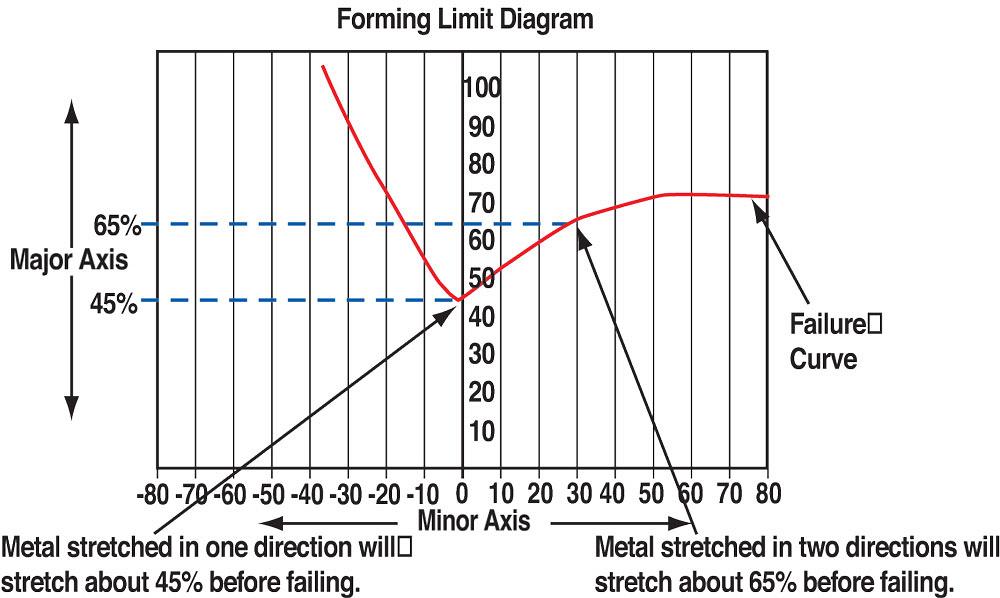
The FLD is a representation of the metal’s deformation limits based on two primary values: the metal’s thickness and its n value, or work hardening exponent.
By knowing how the metal has been deformed as well as its forming limits, you can adjust process variables to ensure that the process is robust. In simple terms, CGA is a way of measuring the forming severity of a formed part (see Figure 1 ).
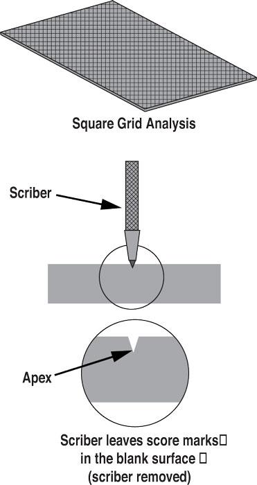
Those of you who have been in the stamping or die building business for numerous years might say, “Circle grid analysis is nothing new to me; I was dong that 40 years go. We would spare blue dye on a blank, let it dry, scribe a series of squares on the surface, and then deform the blank and analyze the metal flow patterns.”
It’s true that square grind analysis helped determine metal flow patterns, but no method was available at the time to measure each deformed square accurately. This prohibited users from determining the forming severity of the part. Today, of course, new software and special cameras can do this.
Keep in mind that scribing a pattern onto a blank leaves a score mark, which could propagate a split (see Figure 2 ).
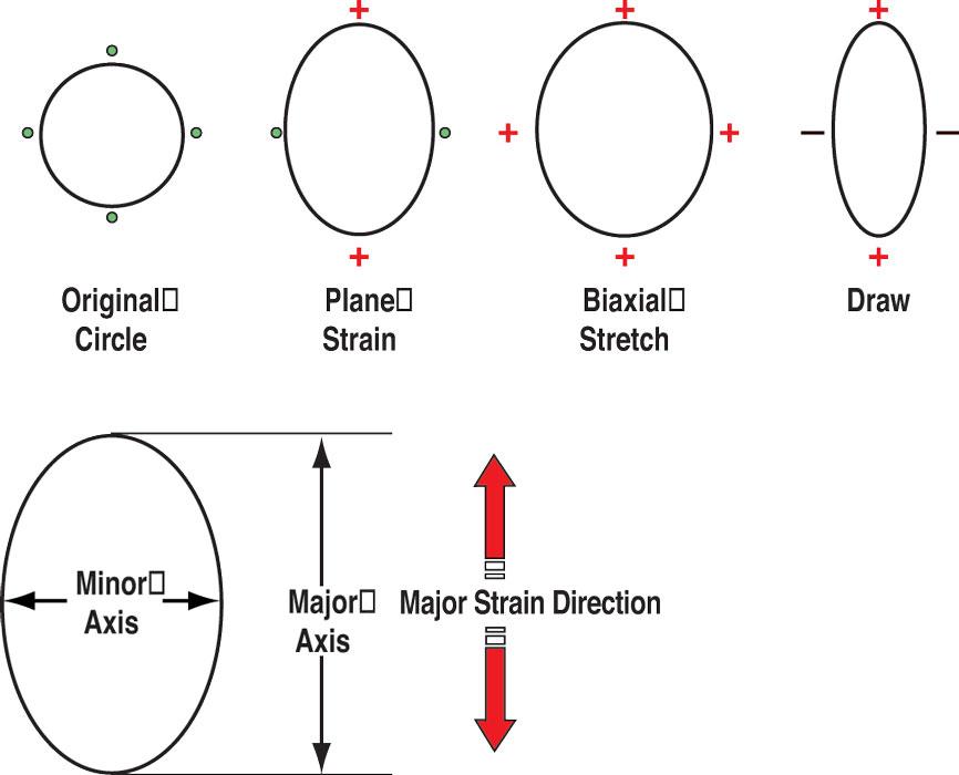
To understand how CGA can be used to solve for splits, you first must understand how metal deforms. The three primary modes of deformation are:
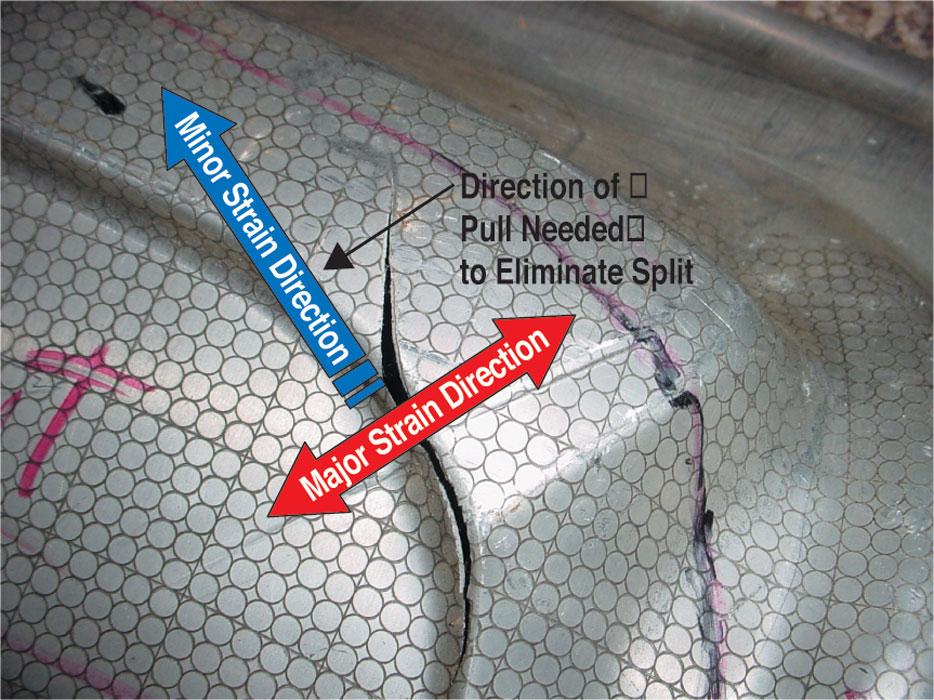
The longest portion of the deformed circle is the major axis tells you the major strain direction (see Figure 3 ).
Steel that is starched or strained in one direction will not elongate as far as steel that is stretched in both directions (see Figure 4 ). Therefore, the thinnest area of a part might not be the area most likely to fail. This is an important fact for troubleshooting draw dies and puts a new spin on problem-solving techniques.
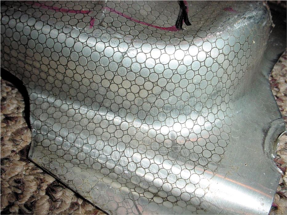
Figure 1
In simple terms CGA is a way of measuring the forming severity of a formed part.
CGA can help you determine in which strain state the metal is failing. For example, assume you have a split in a part and have determined the steel is falling in plane strain (no change in the the minor axis, and a positive change in the major axis). You can analyze the major strain direction and see what you can do to stretch the metal more in the minor axis. This may require adding a draw bead or metal gainer in an area that will force the metal to be cut out as scrap ( see Figure 5 ).
You don’t have to do a full-blown CGA to determine corrective action. Spraying blue dye on your blank, scribing some circles with a pair of dividers, and measuring how the circle has deformed will help you to determine the stain state and direction. Remember, you’re not trying to predict the forming severity of the part; you’re just trying to eliminate the split.
To remain competitive, today’s tooling professionals have to abandon the trial-and-error method of solving problems and start using more databased processes. Diemaking and troubleshooting is not an art; it is a science. Lose the diemaker title and become a dieologist.
Until next time… Best of luck!


The Fabricator is North America's leading magazine for the metal forming and fabricating industry. The magazine delivers the news, technical articles, and case histories that enable fabricators to do their jobs more efficiently. The Fabricator has served the industry since 1970.
start your free subscription
Easily access valuable industry resources now with full access to the digital edition of The Fabricator.

Easily access valuable industry resources now with full access to the digital edition of The Welder.

Easily access valuable industry resources now with full access to the digital edition of The Tube and Pipe Journal.

Easily access valuable industry resources now with full access to the digital edition of The Fabricator en Español.
In this episode of The Fabricator Podcast, Caleb Chamberlain, co-founder and CEO of OSH Cut, discusses his company’s...


