


Research Engineer, Manufacturing and Metals Research
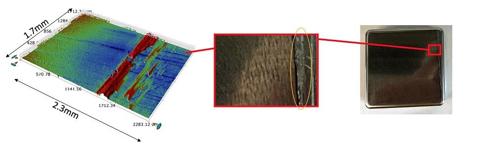
FIGURE 1. The red area on the right is the deposit area on a bare D2 insert tested with 61AUS lubricant. The profile of that deposit is shown on the left.
Editor’s Note: Researchers at the Oakland University Center of Advanced Manufacturing and Materials (CAMM) recently conducted a study to determine which combination of die material, die surface treatment, and lubricant was most favorable for preventing galling when stamping aluminum structural parts. This research is presented in three parts. Part I reported results for D6510 and S0050A die materials with no surface treatments. Part III will discuss results for nitrided and hard-chromed D6510 and S0050A inserts.
The researchers’ goal was to determine galling onset of bare D2 and diamond-like-carbon (DLC) coated (Cr + CrN + a-C:H:W + a-C:H) inserts in contact with 2.5-mm-thick aluminum sheet 5754 and to quantify the influence of lubrication, contact force, and initial roughness of the die surface. The design of the tool is described in detail in “Measuring friction for stamping of UHSS.” The experimental methodology was the same as in Part I.
The researchers examined the inserts and took profile measurements of the galling area using a Bruker profilometer. Figure 1 shows the bare D2 inserts when galling was determined for 61AUS lubricant, as well as the profile of the deposit shown on the left side. The red area on the profile is the area of the deposit.
Pulling force in this test configuration characterized the friction forces applied from both sides of the sheet pulled between two flat inserts clamped together with the draw bead simulator. The coefficient of friction (COF) was calculated as a ratio of the pulling force and doubled clamping force accounting for two friction surfaces. Clamping force was a constant value during the test, since it was driven by the pressure in the hydraulic cylinder of the draw bead simulator. Therefore, the COF curve versus sliding displacement was proportional to the pulling force and provided the experimental COF value, which can be applied for numerical simulation as an additional benefit of this study.
The COF curve for 55-kN clamping force with bare D2 insert lubricated with 61AUS mill oil is presented in Figure 2. This curve was one of the possible ways to determine galling on the inserts. The increase of COF proportional to the pulling force is the sign of the galling initiation. This increase can be interpreted as an additional resistance from the local area where a particle is welded to the die surface. This particle created a local but rather significant resistance to the material flow along the insert surface by making a local indent into the sheet surface, which left a scratch on the surface of the tested strip parallel to the pulling direction. A slight rise of the curve was observed at 50-kN clamping force which corresponded to 28 MPa of average contact pressure and indicated galling initiation. A more obvious rise of COF was observed with further increase of the clamping force.
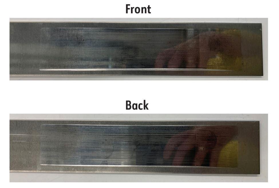
Scratches on the sample of bare D2 with 61AUS lubricant are illustrated in Figure 3.
Tests of D2 with DLC coating with both lubricants showed no galling and low COF. For the tests with 61AUS at 100-kN clamping force, the maximum pulling force (15.8 kN) exceeded the yield threshold of the sheet material (14.5 kN) measured experimentally based upon the tensile test of the tested strips. No galling was observed in the inserts.
For the tests of DLC-coated D2 inserts using DC2-90 lubricant, the clamping force was increased all the way up to 200 kN, which is the maximum possible force provided by the hydraulic pump. No galling was observed in the inserts, even though COF increased for higher forces.
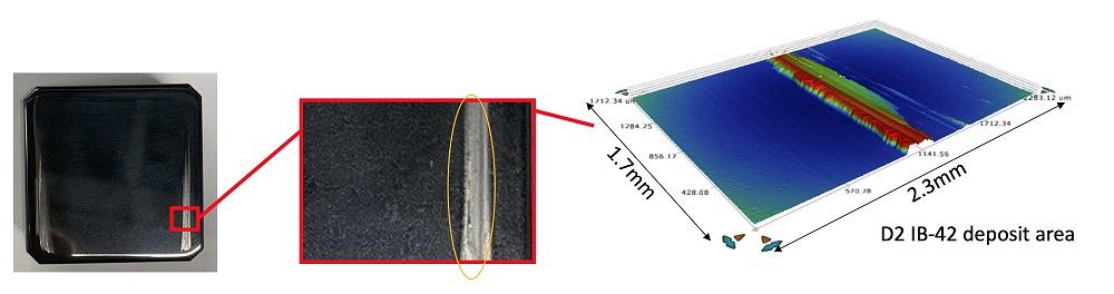
The only condition in which galling was observed for DLC-coated D2 steel was the dry condition with no lubricant. The D2 insert with DLC coating is shown after this experiment in Figure 4. The profile of deposit is shown on the right, and the red area on the profile is the area of deposit.
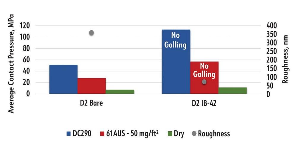
Figure 5 summarizes the average contact pressure galling threshold level correlated with the roughness of the inserts before the test, which was 358 nm for bare D2 inserts and 71 nm for DLC-coated D2 tool steel. For the bare D2 inserts with 50 mg/ft.2 of 61AUS, galling started at 28 MPa of average contact pressure; for the bare D2 inserts with DC2-90, galling started at 51 MPa of average contact pressure; and for the dry condition, it started at 7 MPa of average contact pressure. For DLC-coated D2 with 50 mg/ft.2 of 61AUS and DC2-90 lubricants, no galling was observed in the whole range of contact pressures. For the dry condition, galling started at 11 MPa of average contact pressure. This indicates that having DLC coating on D2 base and having it very well polished provides superior resistance against galling.
This research project was funded in part by the United States Council for Automotive Research with contributions from Novelis Corp., which provided 5754 aluminum alloy coil; Ionbond LLC, which performed coatings of tested inserts; and Quaker-Houghton, which provided lubricants and technical recommendations for application.

Professor and Director
Oakland University Center of Advanced Manufacturing and Materials (CAMM)

PhD Candidate
Oakland University Center of Advanced Manufacturing and Materials (CAMM)


The Fabricator is North America's leading magazine for the metal forming and fabricating industry. The magazine delivers the news, technical articles, and case histories that enable fabricators to do their jobs more efficiently. The Fabricator has served the industry since 1970.
start your free subscription
Easily access valuable industry resources now with full access to the digital edition of The Fabricator.

Easily access valuable industry resources now with full access to the digital edition of The Welder.

Easily access valuable industry resources now with full access to the digital edition of The Tube and Pipe Journal.

Easily access valuable industry resources now with full access to the digital edition of The Fabricator en Español.
In this episode of The Fabricator Podcast, Caleb Chamberlain, co-founder and CEO of OSH Cut, discusses his company’s...


