


Contributing Writer

The limiting draw ratio (LDR) is the relationship between the edge of the draw punch and the edge of the blank, or the ratio of the maximum blank diameter that can safely be drawn into a cup.
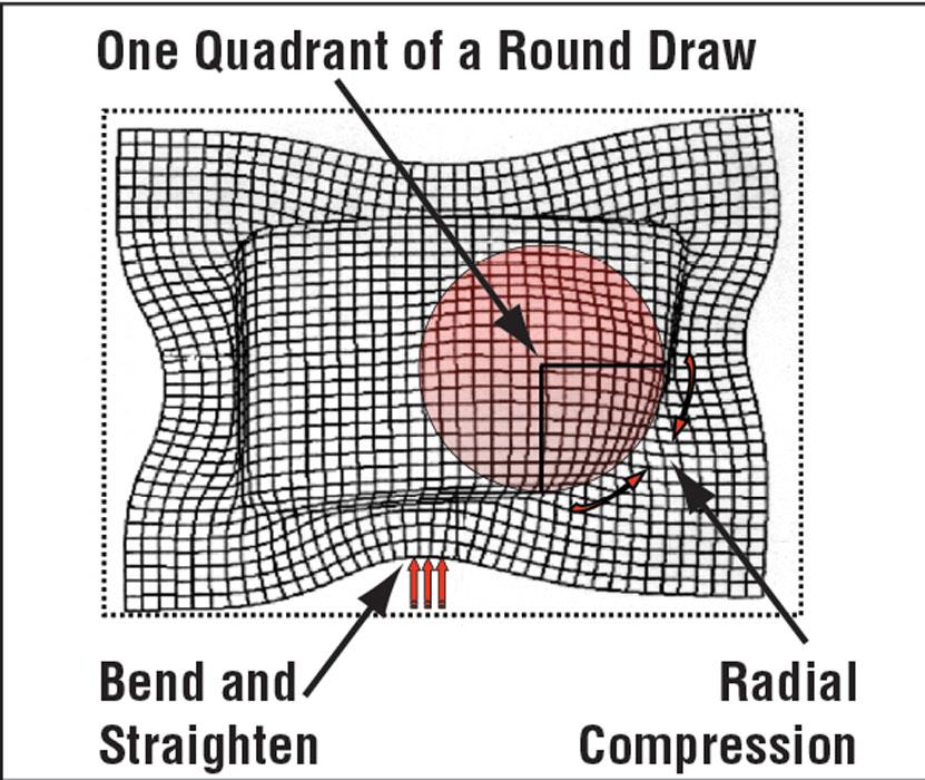
To understand this concept better, consider how an axial symmetrical cup is drawn. A cylinder starts out as a simple round blank. To transform the round blank into a small cylinder shape, you must add radial compression. In other words, for the larger-diameter blank to become the smaller-diameter cup, the metal must flow inward toward the centerline of the cup simultaneously as it compresses together.
If the metal is not controlled, the flange will be severely wrinkled (see Figure 1 ). A great deal of circumferential compression will cause the metal to get thicker at the open end of the cup or the flange.
The key thing to remember is that metal in compression has a great resistance to flow. If too much surface area is outside of the punch, the metal resists flows inwards. This results in excessive stretching of the material and possibly splitting.
A general rule is to use a blank no larger than two times the punch diameter. If the blank to make the parts needs to be bigger than that, you might have to use more than a single drawing station to make the part. When more than one operation is necessary, the LDR percentage will change.
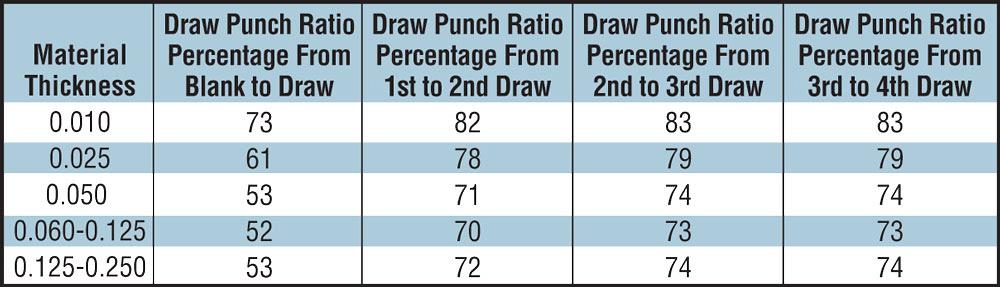
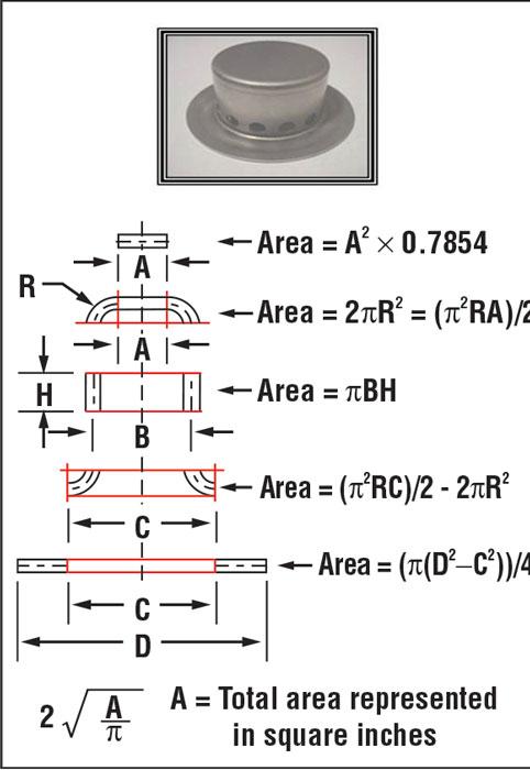
To calculate the approximate number of stations needed for drawing a round shell, you need to know your metal’s thickness and the blank diameter required to make the part. You also need a draw reduction chart for your process (see Figure 2 ). You can calculate the blank diameter by determining the surface area of the part and mathematically converting it back into a round, plant blank (see Figure 3 ). You also can determine the blank size based on the weight of your part. Every metal has a certain weight. For example, steel weighs 0.283 pounds per cubic inch. In other words, a 1-in. cube of steel weighs 0.283 lbs. If you know the metal’s thickness and weight, you can calculate the surface area of the blank.
Don’t forget to add the necessary extra material for trim stock.
Take, for example, a part made from 0.05-in. draw-quality steel. It requires a blank that is 10 in. in diameter. The final diameter of the part will be 2.5 in. By referencing a draw reduction chart, you can determine that the first draw reduction percentage is 53, so the first drawing punch must be at least 53 percent of the blank diameter, or at least 5. 3 in. in diameter.
Because the part is smaller in diameter than 5.3 in., it requires additional drawing operations. The second draw reduction percentage for 0.05-in. -thick materials is 71. Multiplying 5.300 in. by 71 percent equals 3.763 in., which represents the maximum diameter of the second drawing punch.
The part is smaller in diameter than 3.763 in., though, so it requires another drawing operation. The third draw reduction percentage for 0.050-in.-thick material is 74 percent. Multiplying 3.763 in. by 74 percent equals 2.785 in. by 74 percent equals 2.060 in. This is smaller than the finished part diameter, so no more drawing operations are required.
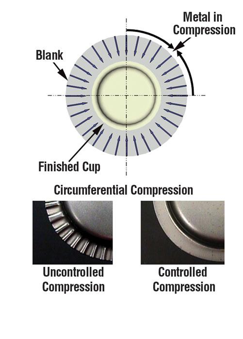
Figure 1
When compression is controlled, the
flange is flat. When compression is not
controlled, the flange is severely wrinkled.
Therefore, to make a part that is 2.5 in. in diameter with a blank that is 10 in. in diameter and made of 0.05-in.- thick, low-carbon, draw-quality steel requires four drawings stations.
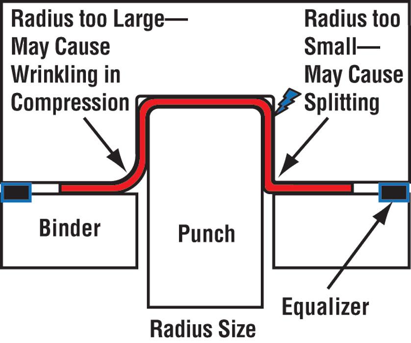
Three crucial radii affect metal flow:
The die entry radius is the most influential. It creates a restrictive force by causing the metal to bend and unbend during the drawing process. If the die entry is too large, the metal is is in compression, and very little restrictive force is keeping the metal from flowing in. Then the radial area of the part may wrinkle (see Figure 4 ). The metal is being forced to unwrinkle in the walls of the drawn shell, which creates a resistance flow, resulting in more stretch.
Different metals require different radii. For instance, drawing aluminum typically requires radii up to one-third greater than the size of radii used when drawing soft steel. A good rule for drawing steel is to use six to eight times the metal thickness.
The punch radius, located at the top of the punch, also is a critical radius. The size of the punch radius often determines how much stretch will occur and how much metal will be pulled from the blank holder.
Using a very large radius on the punch, along with a high blank holder force or draw beads, will force a great deal of stretch and less drawing to occur. Using a large radius on the punch with a low blank holder force will result in a combination of flow, and some stretch.
A small radius on the draw punch will force the metal to be pulled from the blank holder, and very little stretch will occur in the product area. A small radius usually is acceptable only when the LDR is not being defined.
A medium-size radius on the punch, combined with an acceptable LDR is optimum for stretch distribution in the radial area. Although often viewed as poor practice, it is sometimes helpful to retard metal from thinning out in this area.
The profile radius represents the outside profile of the drawn shell. Its size greatly affects the amount of metal flow that takes place during the drawing process (see Figure 5 ). Larger-profile radii allow more metal to flow inward than smaller radii.
Until next time, best of luck!


The Fabricator is North America's leading magazine for the metal forming and fabricating industry. The magazine delivers the news, technical articles, and case histories that enable fabricators to do their jobs more efficiently. The Fabricator has served the industry since 1970.
start your free subscription
Easily access valuable industry resources now with full access to the digital edition of The Fabricator.

Easily access valuable industry resources now with full access to the digital edition of The Welder.

Easily access valuable industry resources now with full access to the digital edition of The Tube and Pipe Journal.

Easily access valuable industry resources now with full access to the digital edition of The Fabricator en Español.
In this episode of The Fabricator Podcast, Caleb Chamberlain, co-founder and CEO of OSH Cut, discusses his company’s...


