


Contributing Writer

A lot of the information that we learn as toolmakers s passed down to us and, unfortunately, that can include myths based on one individual’s personal experience on that one job he built back in 1972. You know what I mean.
It amazes me how many decisions are made in the toolroom with little or no data to back them up. We often design dies in a certain fashion simply because that’s how we were taught to do it.This tool and die trade has been passed down from generation to generation, and unfortunately, not all learned concepts apply to every situation. If you have been a loyal reader of “Die Science,” you may have noticed that I have become quite fluent in phrases such as “generally speaking” or “in most cases” or “a large portion of the time.” Why? Because rarely does “never” or “always” apply to veery tool design or troubleshooting process.
Following are some of the myths that may have been passed down to you.
Although hard sheet typically is more difficult to form than soft steel, the steel’s hardness is not proportional to its mechanical properties, such as its n value or elongation percentage.
For example, a Rockwell hardness rating of 55 on the B scale doe snot tell you how stretchable the material is, nor does it tell you its drawability. Checking the material’s hardness gives you one piece of concrete data: how hard the steel is.
However, the hardness of a given steel sample can be used for comparative analysis. Large differences in a metal’s hardness most certainly will indicate a change in formability. Keep in mind, though, that several speciality had steels available today stretch more than softer steels.
When you’re trying to determine a sheet steel’s stretchability and drawability, seek concrete values such as the metal’s elongation percentage or its n and r values.
Sometimes a big radius is less desirable than a smaller one, especially when drawing parts that go through multiple reductions.
To understand this concept, you first must understand the basic concept behind the limiting draw ratio. It is among the most important elements to be considered when attempting to deep-draw a round cup or any area of a part with a radial feature, such as the corners of square draw.
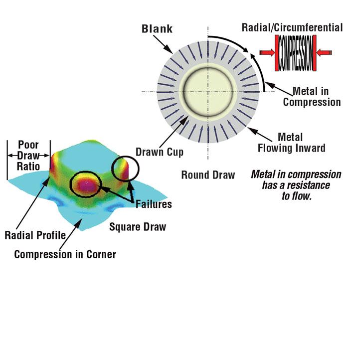
Figure 1
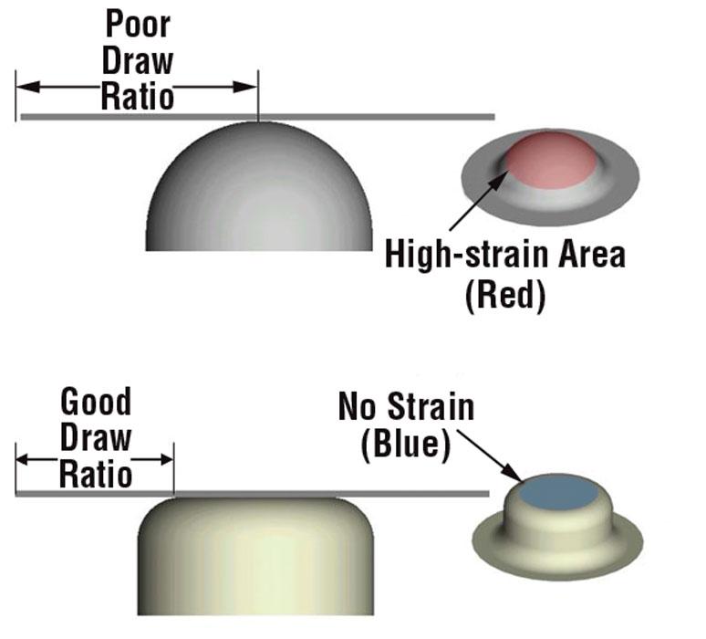
The draw ratio is the relationship between the edge of the draw punch and the distance to the blank edge.
The draw ratio is the relationship between the edge of the draw punch and the distance to the blank edge (see Figure 1 ). The ratio must fall within acceptable limits to allow metal to flow.
During forming the blank is forced into circumferential compression in radial areas of the part. This compression creates a resistance flow. If the draw post is too small or too far from the blank edge, the resistance will be too great, and the metal will stretch and thin to the point of failure. If the punch is the appropriate distance from the blank edge and the die entry radius is acceptable, the blank holding pressure will be correct, and the metal will flow freely, progressively thickening as it enters the die cavity.
Using a large radius such as a dome will force the metal to be contacted as far as it possibly can be from the blank edge. This will result in more stretching and thinning in the top portion of the dome. If this part must go through multiple reductions or reworking, the thinned-out, work-hardened material is subject to failure.
However, if the radius is reduced, the punch makes contact much closer to the blank edge, allowing the metal to flow inwards rather than stretch. The flat portion of the top of the cup will contain unstrained material of original thickness (see Figure 2 ).
Although all automotive body panels dies may have blank holders and be designed as basic drawing dies, in some instances, no true drawing is taking place.
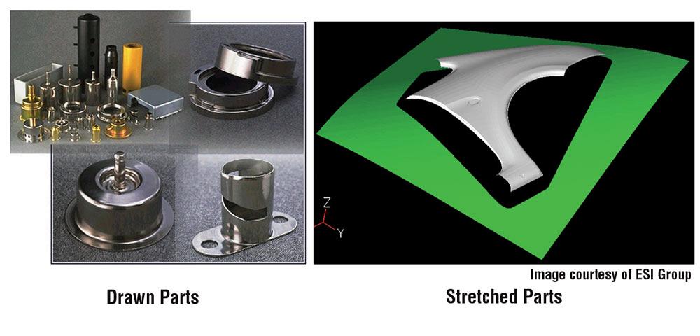
To understand this concept, you first need to understand the difference between drawing and starching. Drawing is the displacement of surface area through the process of inward plastic flow. Stretching is the increase of surface area caused by tension.
A shallow roof panel is a good example of a stretched part, because a lock bead stops off the material flow. A body side requires both drawing and stretching.
True drawing operations obtain most of the part shape by plastic flow rather than stretch. Very simply, if the blank profile does not change its size or shape during forming, it’s being starched, not drawn (see Figure 3 ).
Until next time… Best of luck!


The Fabricator is North America's leading magazine for the metal forming and fabricating industry. The magazine delivers the news, technical articles, and case histories that enable fabricators to do their jobs more efficiently. The Fabricator has served the industry since 1970.
start your free subscription
Easily access valuable industry resources now with full access to the digital edition of The Fabricator.

Easily access valuable industry resources now with full access to the digital edition of The Welder.

Easily access valuable industry resources now with full access to the digital edition of The Tube and Pipe Journal.

Easily access valuable industry resources now with full access to the digital edition of The Fabricator en Español.
In this episode of The Fabricator Podcast, Caleb Chamberlain, co-founder and CEO of OSH Cut, discusses his company’s...


