


Contributing Writer

Two main characteristics need to be addressed in the design of a carrier strip: travel (or the amount of stretch and flex needed) and carrier strength.
When certain types of parts are made in a progressive die, the attachment strip must flex both toward the centerline of the part and vertically with respect to different die heights or drawing depths. Parts requiring deep drawing or multiple reductions are classic examples. In addition, the direction inn which the part is drawn often dictates the amount of flex needed.
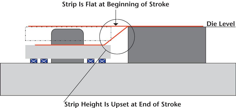
Figure 1 shows a poorly designed strip carrier used for drawing. This strip design does not allow for metal to flow inward without upsetting the progression. As the metal flows inward, the strip will be pulled out of progression. In addition, if the part is drawn up, no vertical movement has been allowed, as illustrated in Figure 2 .
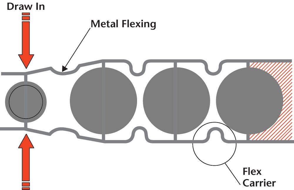
Figure 3 shows an example of an ideal stretch web development. This web allows for both horizontal and vertical movement of the attachment carrier, allowing the part to remain on progression during drawing and vertical movement without pulling the remaining part out of progression. Each part can move independently.
While the carrier must be deigned to flex with the metal’s movement, it also must remain strong enough to resist bending during the feeding process.
It takes about 10 percent of the part’s weight to move it horizontally. For instance, if the finished part weighs 1 pound, 1/10 lb. of force is needed to move it. If there are eight progressions, the total strength of each carrier or flex attachment must resist 8 lbs. of force without bending.
Although no formulas exist for determining carrier strength, judgment should be based on material type and thickness. If a carrier is designed and built too weak, stiffening ribs can be added before or after the cutting process to increase its strength.
Developing the carrier is a relatively simple process. The key is to develop enough length of line in the attachment web to allow for the needed flex. Two primary methods are used to develop the carrier— simulation software and wax cutting.
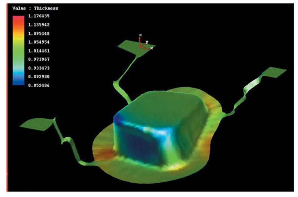
Simulation Software. One way to develop the carrier, and perhaps the most effective way, is to simulate the stretching of the carrier using forming simulation software. The software can provide critical carrier results for an infinite number of material types and thickness.
Figure 4 show a simulation file of an attachment carrier being deformed during a deep-drawing process. The flex web is being deformed both horizontally and vertically. This simulation provides data such as the finished thickness, geometry, and the probability of tearing. Simulation also can determine the amount of flexing that will take place during the feeding process, although this function is not widely used.
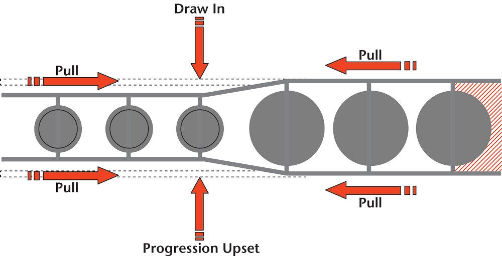
Figure 1
This example of a poorly designed strip carrier used for drawing shows that the design does not allow for metal to flow inward without upsetting the progression. As the metal flows inward, the strip will be pulled out of progression.
Wax Cutting. But what about stampers who don’t have the luxury of using simulation software?
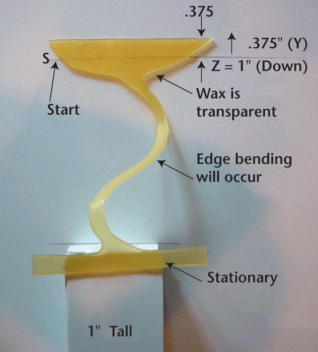
For many years carriers have been developed manually, without software. The process requires the use of bee’s wax (available in sheet form in a variety of thickness), a sharp knife or scriber, and a proposed carrier test shape. The wax is cut to the proposed shape of the attachment web and manually stretched horizontally and vertically with respect to the metal’s movement. If the wax breaks during this process, the metal will likely break too
Changes in the carrier can be made to the length of line until the stretch is obtained without breaking. This finished geometry of the wax will closely represent the finished geometry of the metal. Figure 5 shows this process with a carrier that requires 1 inch of vertical travel and 0.375 in. of horizontal travel.
Note that for the forming of high-strength materials, carrier length should be very liberal. High-strength materials do not have the ability to stretch that lower-strength material have.
With the popularity of simulation software rising, wax cutting is becoming less popular.
Carrier strip design is one of the most important factors controlling the success of a progressive die. The carrier must be designed to adsorb the vertical motion and horizontal metal flow during forming that can pull parts out of progression. Whatever carrier style you select, it must be strong enough to support smooth feeding but flexible enough to maintain pitch. Good luck!


The Fabricator is North America's leading magazine for the metal forming and fabricating industry. The magazine delivers the news, technical articles, and case histories that enable fabricators to do their jobs more efficiently. The Fabricator has served the industry since 1970.
start your free subscription
Easily access valuable industry resources now with full access to the digital edition of The Fabricator.

Easily access valuable industry resources now with full access to the digital edition of The Welder.

Easily access valuable industry resources now with full access to the digital edition of The Tube and Pipe Journal.

Easily access valuable industry resources now with full access to the digital edition of The Fabricator en Español.
In this episode of The Fabricator Podcast, Caleb Chamberlain, co-founder and CEO of OSH Cut, discusses his company’s...


