


Contributing Writer
Another key factor to controlling metal flow is the use of the forming die’s blank holder. There have been numerous studies regarding the depth of draw that can be achieved with respect to the blank holder pressure. While most of these studies are relevant and accurate, the question remains: When should the blank holder be used to squeeze and restrict metal flow, and when should a different method be used?
Blank Holder Basics
The blank holder, often referred to as the draw pad or binder, is typically a thick tool steel ring, either flat or contoured, that surrounds the draw punch and controls the inward flow of metal. It usually is pressure-loaded meaning that it sits on top of a pressure system such as coil, urethane, or gas springs (see Figure 1 ).
The blank holder also can get its necessary force from an external source, such as a press cushion. Press cushions, are plates mounted underneath the bolster plate of the press. They move vertically and typically are activated by air or hydraulics.
Press cushions use cushion pins to transfer the force to the bottom of the blank holder (see Figure 2 ). Speciality systems use individual hydraulic cylinders to provide the necessary force. This allows force to be changed in different areas around the punch.
Consistency Challenge
If your goal is to obtain extreme consistency, avoid using blank holder pressure to control metal flow. Despite very popular misconceptions, the true function of a blank holder is not to squeeze the metal and create a resistance to flow. The function of a draw pad is to keep the metal from wrinkling during inward flow and radial compression.
If you find yourself constantly changing the pressure in your system in an effort to combat splits and wrinkles, you’re most likely trying to control metal flow by squeezing the metal tighter or by not squeezing it and thus letting it go.
Good luck with consistency.
I am in no way saying that draw pad pressure can’t be used to create a restrictive force, nor am I stating that limited success can’t be achieved by applying more or less blank holding force. However, I am saying that achieving consistency will be more difficult this way.
Figure 1
The blank holder usually is pressureloaded,
which means that it sits on top of
a pressure system such as coil, urethane,
or gas springs.
Why? First of all, unless you have a speciality system such as electronic shimming or programmable cushion, draw pad pressure normally increases during the drawing process. As the draw pad travels downward, the pressure on the blank when using a stand-alone gas spring can double during the downstroke.
This is a problem because the more pressure that is applied to the blank, the greater the friction, and the greater the friction, the greater the temperature. As forming temperatures change in the die, so does the coefficient of friction change with respect to the additives in the lubricant.
In simple terms, the more you squeeze the lubricant, the more it affects friction. When you use blank holder pressure alone, you are relying solely on the frictional value created by the inconsistent draw pad pressure and the coefficient of friction created by the lube. Die temperature, lubricant viscosity, press deflection, different forming speeds, the surface topography of the metal, and lubrication application methods will most likely have a great effect on the success of your drawing process.
To compound matters, keep in mind that as the metal flows inward, the draw ratio is changing. The amount of metal that is trapped between the die face and the draw pad is decreasing as the metal flows inwards. This essentially results in more pressure being concentrated on a smaller area of the blank during the drawing process.
Imagine holding a sheet of metal between your forefinger and thumb. Now imagine me asking you to apply just the right amount of force to the metal so that when I pull it through your fingers, it stretches 10 percent. I don’t want 9 percent or 11 percent. And I want this consistent 10 percent stretch for the next 10,000 times I pull it through you fingers.
Odds of success? Pretty slim, huh?
Now, let’ s change the circumstances so that they mimic a drawing operation full reliant on pressure and lubrication. Here’s the new request: Hold the imaginary sheet metal between your forefinger and thumb, but now I am going to put lubricant on the metal. I want you to apply just the right amount of pressure to the blank, making sure that your pressure increases as I pull it through your hands. I want 10 percent stretch consistently for the next 10,000 times.
Lubricants usually contain additives that react to forming temperatures. For instance, if you use a chlorinated lubricant for drawing, once the temperature between the die and the sheet drops to less than one-half of its original value (see Figure 3 ).
What’s your chance of getting consistent parts? Play the Lotto—the odds of winning are better.
Restrict, Don’t Squeeze
Equalizers, often referred to as standoffs or draw pad spacers, are blocks of impact-resistant tool steel inserted into the draw pad or die face. Their function is to maintain a specified gap between the die face and the blank draw pad, regardless of excessive pressure that may be exerted on the draw pad.
Figure 2
Press cushions use cushion pins to transfer
the force to the bottom side of the blank
holder.
Equalizers prevent the metal from being squeezed during the drawing process while ensuring the gap between the die face and draw pad remains small enough to keep the metal from wrinkling. They also help reduce both draw pad and die face detection, and they allow for simple adjustment to be made for minor thickness variations and mechanical property changes that occur in the sheet metal throughout the coil.
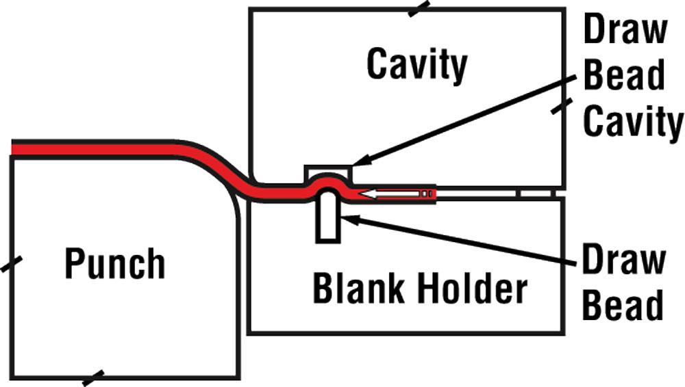
Consider using draw beads to restrict and control metal flow. Think of draw beads as “speed bumps” for metal; they create a restrictive force by bending and unbending the material (see Figure 4 ). The height and geometry of the draw bead control the restrictive force, and you can regulate metal flow by raising or lowering their height.
Making It Work
As we’ve seen, using blank holder pressure to control metal flow is not the ideal situation, but it is sometimes necessary. Adding draw beads often requires that you use more material to make the part. Also, keep in mind that die deflection makes it almost impossible not to squeeze the metal, especially with larger drawing and stretching dies.
The key is to avoid squeezing whenever practical.
Until next time… Best of luck!


The Fabricator is North America's leading magazine for the metal forming and fabricating industry. The magazine delivers the news, technical articles, and case histories that enable fabricators to do their jobs more efficiently. The Fabricator has served the industry since 1970.
start your free subscription
Easily access valuable industry resources now with full access to the digital edition of The Fabricator.

Easily access valuable industry resources now with full access to the digital edition of The Welder.

Easily access valuable industry resources now with full access to the digital edition of The Tube and Pipe Journal.

Easily access valuable industry resources now with full access to the digital edition of The Fabricator en Español.
In this episode of The Fabricator Podcast, Caleb Chamberlain, co-founder and CEO of OSH Cut, discusses his company’s...


