Contributing Writer
- FMA
- The Fabricator
- FABTECH
- Canadian Metalworking
Categories
- Additive Manufacturing
- Aluminum Welding
- Arc Welding
- Assembly and Joining
- Automation and Robotics
- Bending and Forming
- Consumables
- Cutting and Weld Prep
- Electric Vehicles
- En Español
- Finishing
- Hydroforming
- Laser Cutting
- Laser Welding
- Machining
- Manufacturing Software
- Materials Handling
- Metals/Materials
- Oxyfuel Cutting
- Plasma Cutting
- Power Tools
- Punching and Other Holemaking
- Roll Forming
- Safety
- Sawing
- Shearing
- Shop Management
- Testing and Measuring
- Tube and Pipe Fabrication
- Tube and Pipe Production
- Waterjet Cutting
Industry Directory
Webcasts
Podcasts
FAB 40
Advertise
Subscribe
Account Login
Search
Die Science: Solving stretch flange problems
Part II: Using a simple processing and troubleshooting tool
- By Art Hedrick
- August 30, 2017
- Article
- Bending and Forming
What Is It Used For?
Almost every conventionally stamped part starts out as flat blank. Processing engineers then decide the process of how to transform this simple flat sheet into the final product geometry. Often part features such as stretch flanges present a problem, especially if the metal is very thin or very strong.
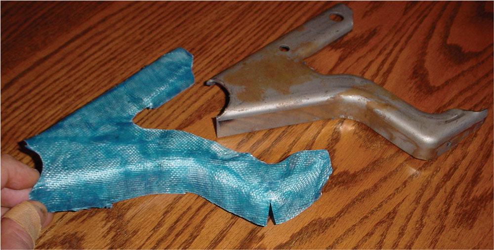
All metals are not the same. Some have good stretch distribution characteristics; others react very poorly when subjected to tension. Using a rubber skin, you can unfold the finished part geometry as if it were a flat blank. Doing so will show you areas of your product that will be subjected to severe stretch and possible failure. It also will show the exact difference in length of line from the flat blank to the finished part, in turn revealing where and how much stretch will occur during forming (see Figure 1 ).
Knowing that these conditions exist might lead you to add a performing die to the process. Preforming is done in an effort to force the metal to stretch more evenly over a larger surface area before the secondary forming process.
Unlike using a one-step stretch flanging process, you can control how the metal starches by using a special stretching punch shape. Then you can simply displace this needed, strategically starched surface area into the final product shape.
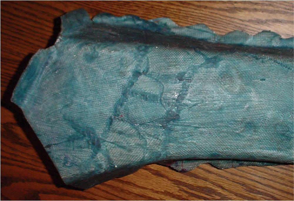
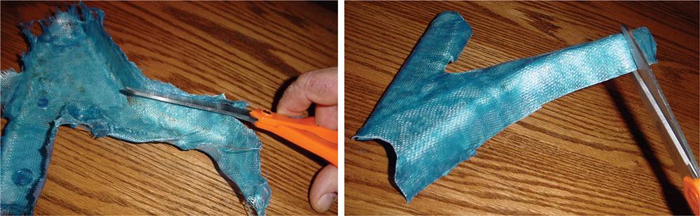
You can also unfold rubber skins to show ways of direct trimming your product. Items such as tabs, weld flanges, and shelves are the most common part, features that are unfolded (see Figure 2 ).
Diemakers also can use rubber skins. By placing the rubber skin directly on the punch of the forming tool, the diemaker can see where features such as trim lines fall on the forming punch. Anything falling outside of the trim or product area can be changed to reduce the forming severity of the part. It is also a great tool for showing customers what will likely happen during the forming process.
What Materials Do I Need?
To make a rubber skin, you will need the following materials:- A part or model of the part. This can be a prototype metal part, a failed production part, a wooden or Styrofoam® model, a stereolithography model, or anything else representing the final product shape. If you will be using a very porous material such as Styrofoam, make sure that you paint the model with latex paint before using it to make a rubber skin. Scribe features such as pierce holes on your model, and they will transfer to the rubber skin.
- A few simple tools. These include an inexpensive paint brush (use the cheapest one you can find because you will have to throw it away), a pair of scissors, and a razor or Exacto® knife.
- Fiberglass cloth. You can get this at most automotive stores. Buy the soft, flexible kind.
- A jar of Modelex® compound. Also known as “Mountains in minutes,” this compound is available in various colors and often is used to make small-scale landscapes for model railroads. You also may want to wear old clothes and rubber gloves when working with this compound. Make this skin on old newspaper in a well-ventilated area.
- Cut up the fiberglass cloth in sizes that are smaller than the part size. Small strips often are better than one large price. You may want to analyze your geometry. There’s no need to be too fussy, because the cloth conforms to the product’s shape (see Figure 3 ).
- Paint the entire part or the area of concern with a thick coat of the molding compound. Don’t worry about using a release agent. Just make sure that the model is not porous.
- Paint both sides of the fiberglass cloth with the compound.
- Apply the coated fiberglass cloth to your part or model, cutting the cloth as necessary to get it to lie right. Use your fingers to press the cloth into the part, making sure that it is conforming to the product’s shape. Continue this process of applying costs of painted fiberglass cloth until you have built up a skin thickness fairly equal to your part’s thickness. One cost of fiberglass cloth and compound is about 0.020 inch thick.
- Paint the part again with a final coat of compound.
- Let it dry overnight. If you are in a hurry, you can use a blow dryer to expedite the drying process.
- Peel off the rubber skin. Part features such as trim lines and hole locations will be transferred to the rubber skin, and you can cut them out using scissors or a razor to match your part’s geometry. You may find it necessary to cut compression flanges and certain features to get the rubber to lie flat (see Figure 4a and 4b ).
- Analyze what happens to the rubber skin when unfolded. Look for severe differences in length of line from blank to finish form.
How Do I Make the Rubber Skin?
Cheap and Effective
Although we have wonderful high-tech tool such as forming simulation, someone still must create the original forming process inputs. By using the data provided by a rubber skin, you can predict failure quickly, effectively, and cheaply as well as correct them.I don’t know about you, but I like cheap. I like quick. And I like effective.
Until next time… Best of luck!
About the Author
Art Hedrick
10855 Simpson Drive West Private
Greenville, MI 48838
616-894-6855
Related Companies
subscribe now
The Fabricator is North America's leading magazine for the metal forming and fabricating industry. The magazine delivers the news, technical articles, and case histories that enable fabricators to do their jobs more efficiently. The Fabricator has served the industry since 1970.
start your free subscription- Stay connected from anywhere
Easily access valuable industry resources now with full access to the digital edition of The Fabricator.
Easily access valuable industry resources now with full access to the digital edition of The Welder.
Easily access valuable industry resources now with full access to the digital edition of The Tube and Pipe Journal.
Easily access valuable industry resources now with full access to the digital edition of The Fabricator en Español.
- Podcasting
- Podcast:
- The Fabricator Podcast
- Published:
- 04/16/2024
- Running Time:
- 63:29
In this episode of The Fabricator Podcast, Caleb Chamberlain, co-founder and CEO of OSH Cut, discusses his company’s...
- Trending Articles
Tips for creating sheet metal tubes with perforations
JM Steel triples capacity for solar energy projects at Pennsylvania facility
Are two heads better than one in fiber laser cutting?
Supporting the metal fabricating industry through FMA
Omco Solar opens second Alabama manufacturing facility
- Industry Events
16th Annual Safety Conference
- April 30 - May 1, 2024
- Elgin,
Pipe and Tube Conference
- May 21 - 22, 2024
- Omaha, NE
World-Class Roll Forming Workshop
- June 5 - 6, 2024
- Louisville, KY
Advanced Laser Application Workshop
- June 25 - 27, 2024
- Novi, MI