


Contributing Writer

Draw Pad Shape
Depending on the part shape, draw pads can be different shapes, sizes, and thickness. Parts with a great deal of contoured shape and curvature often use a pad that is curved with respect to the part shape; square or rectangular parts with flat bottoms usually use a flat pad (see Figure 1 ).
The shape that the sheet metal takes when being formed to the draw pad often is referred to as the wrap. The wrap is crucial to the success of the drawing operation.
The shape that the sheet metal takes when being formed to the draw pad often is referred to as the wrap. The wrap is crucial to the success of the drawing operation.
An undevelopable wrap means that the draw pad will be shaped so that it will force some metal to be pushed up into the draw pad (punch) opening before forming punch contact. This often is desired when attempting to stretch-draw parts with a great deal of shape that must be obtained by stretching or embossing features in the center area of a part.
For example, inner automobile doors often use an undevelopable wrap. Because an inner door is not usually defined as a Class A, or exposed, surface, minor defects caused by the metal being creased before punch contract are permissible. Using an undevelopable wrap to stretch-draw Class A parts often results in surface defects from draw pad contact that are nearly impossible to get rid of.
A developed wrap means the blank, when taking the shape of the draw pad, will not buckle, twist, or crease. This wrap type is desirable when stretch-drawing items such as exposed Class A body panels like outlet doors and fenders.
Draw Pad Thickness
There is no simple formula for determining draw pad thickness, although finite element analysis (FEA) can determine the amount of deflection that will occur.A good rule of thumb is that thickness is better. However, even if the draw pad is thick enough to minimize deflection, the press bolster and ram will deflect.
The pad thickness is a judgment based on the following three factors: 1. The amount of draw pad defection that will occur during the drawing process. Obviously, a thicker draw pad defects less than a thinner pad, but defection will occur regardless of pad thickness. Allowing the pad to deflect severely results in a loss of metal flow control, but it doesn’t take much deflection to cause a drawing problem. A deflection as small as 0.001 inch when drawing thin metal will allow the metal to wrinkle between the draw pad and die face. The use of equalizers helps minimize this effect.
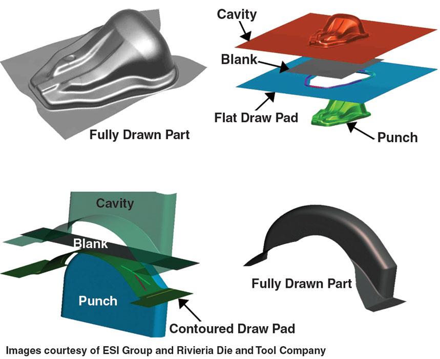
Figure 1
Depending on the part shape, draw pads can be different shapes, sizes, and thicknesses.
Fitting the Draw Pad
Fitting, or spotting, the draw pad is a crucial process in which the pad is ground with respect to the shape of the die face and metal flow conditions.Spotting most often is performed using a hand grinder and a nondrying paint-like substance known as spotting blue or read lead. (For you veteran toolmakers: Yes, that’s that blue stuff that the jokester put on the nose pads of your safety glasses and earpiece of the phone receiver.)
Flat Part= Flat Draw Pad?
There is a major misconception among die designers and diemakers regarding flat draw pads.Most stampers believe that if the part has a flat bottom, such as a cake pan or box, they can simply design a flat draw pad, and the die face and the draw pad perfectly flat, eliminating the need for had spotting.
In reality, while the concept sounds good and the pad will fit perfectly to the die face, metal being compressed often thickens. Compression occurs when metal is allowed to flow into the corners of a radial profile. During forming the corner areas of the blank are forced into radial compression,which creates a resistance to flow. If the resistance is too great, the corners will stretch, possibly resulting in fracturing.
If the draw punch is the appropriate distance from the blank edge, and the die entry radius, lubricant, and material properties are acceptable, the metal will flow freely, progressively thickening on the draw pad and as it enters the die cavity (see Figure 2 ) . If the pressure pad is ground flat, the pressure exerted on the blank will be concentrated in the corners where the metal has thickened.
Remember that in this corner area, the metal already has a resistance to flow caused by radial compression. In addition, an increased resistance is created when the blank-holding pressure is concentrated in the corners. The results is splitting in the corners (see Figure 3 ).
The solution is to hand-grind the draw pad with respect to the ever-changing metal thickness during the drawing process. Doing so increases the gap between the draw pad and the die face in the corners. The amount of metal that is removed during the grinding process depends on the amount of compressive thickening.
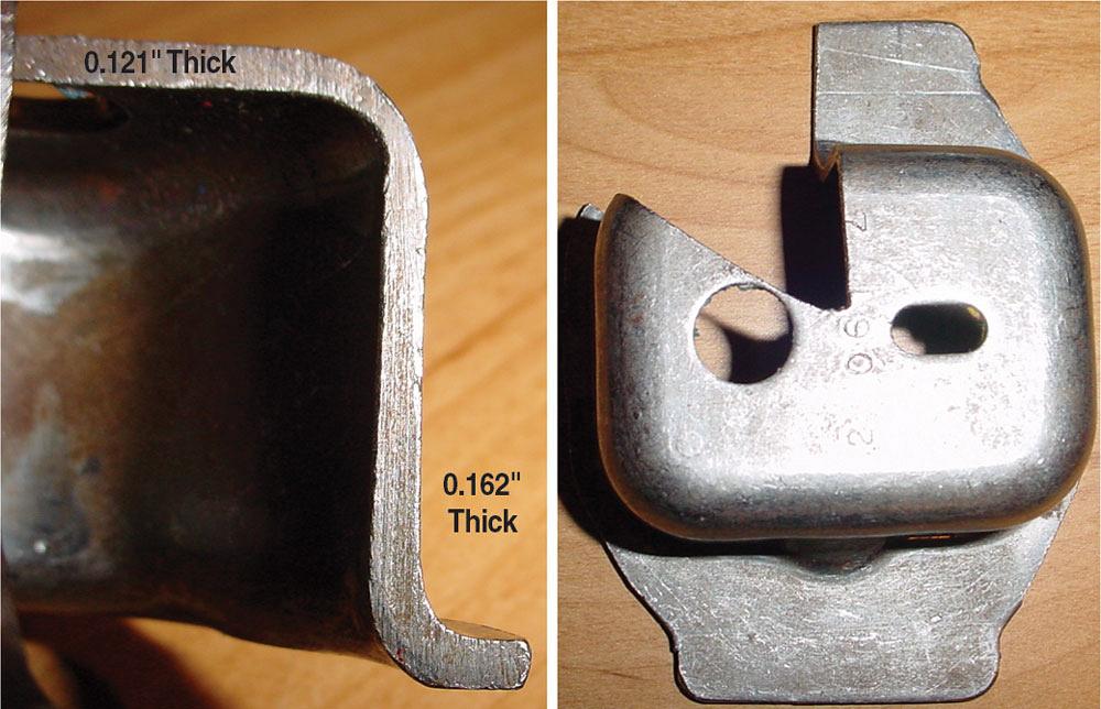
Figure 2
If the draw punch is the appropriate distance from the blank edge, and the die entry radius, lubricant, and material properties are acceptable, the metal will slow freely, progressively thickening on the draw pad and as it enters the die cavity.
Good Spotting Practice
A common question is, Do I spot with the draw pad blocked up parallel, or do I spot the draw pad while it is blocked up parallel and finish and fine-tune the spotting process on the pressure system.There are two reasons for this. First, you can’t preform a running spot on a blocked-up solid draw pad. Second, when spotting on the pressure system, you can grind with respect to deflection that occurs in the pad and the press. Surface-finish, or stone, the draw pad with respect to the metal flow direction until a good, accurate surface finish has been achieved.
The success of a drawing operation depends on numerous factors. Among the most significant is the function of the draw pad. Don’t underestimate the importance of a properly designed, fir, and finished draw pad.
Until next time… Best of luck!
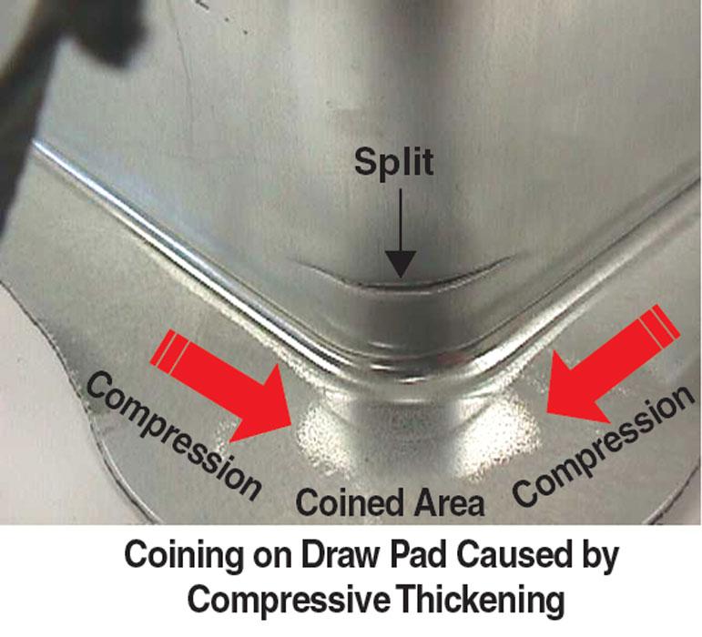
Figure 3
An increased resistance is created when the blank-holding pressure is concentrated in the corners, which causes the corners to split.


The Fabricator is North America's leading magazine for the metal forming and fabricating industry. The magazine delivers the news, technical articles, and case histories that enable fabricators to do their jobs more efficiently. The Fabricator has served the industry since 1970.
start your free subscription
Easily access valuable industry resources now with full access to the digital edition of The Fabricator.

Easily access valuable industry resources now with full access to the digital edition of The Welder.

Easily access valuable industry resources now with full access to the digital edition of The Tube and Pipe Journal.

Easily access valuable industry resources now with full access to the digital edition of The Fabricator en Español.
In this episode of The Fabricator Podcast, Caleb Chamberlain, co-founder and CEO of OSH Cut, discusses his company’s...


