


Getting back to air forming and bending basics on the press brake
Addressing long-held misunderstandings in the sheet metal industry about how radius is formed
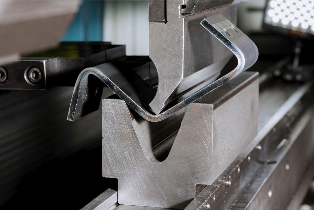
ZhakYaroslavPhoto/iStock/Getty Images Plus
Q: I’ve been struggling to understand how the bend radius on a print (which I specify) correlates to tool selection. For example, we are currently having some issues with some parts made from 0.5-in.-thick A36 steel. For these parts, we use a punch with a 0.5-in. radius and a 4-in. die. Now, if I use the 20% rule and multiply the 4-in. die opening by 15% (for steel), I get 0.6 in. But how does the operator know to use the 0.5-in.-radius punch if the print calls for a bend radius of 0.6 in.?
A: You have hit upon one of the biggest issues facing the sheet metal industry. This is a misunderstanding that both engineering and the shop floor must deal with. To solve this problem, we’ll start with the root cause—that is, the two methods of forming and the lack of knowledge about the differences between them.
Bottoming and Air Forming
From the advent of the powered press brake in the 1920s to the present day, operators have formed parts with bottom bending, or bottoming. Even though bottoming has been losing favor over the last 20 to 30 years, the bending method still permeates our thinking when we bend sheet metal.
Precision-ground tooling entered the market in the late 1970s and changed the entire paradigm. So, let’s look at how precision tools differ from planer tooling, and how the shift to precision tooling changed the industry, and what it all has to do with your question.
In the 1920s, forming changed from folding on a leaf brake to forming into a V die with a matching punch. A 90-degree punch would be coupled with a 90-degree V die. The change from folding to forming was a major leap forward for sheet metal. It was faster partly because the newly developed press brake was powered—no more manual folding of every bend by hand. Plus, press brakes could bottom bend, which boosted accuracy. Backgauging aside, the increase in accuracy can be credited to the punch nose stamping its radius into the inside bend radius of the material. This was accomplished by forcing the nose of the tool to a less-than-material-thickness position. And as we all know, if we can achieve a consistent inside bend radius, we can calculate the correct values for the bend deduction, bend allowance, outside setback, and k-factors, regardless of the type of bend we’re making.
It was quite common to bottom a very sharp inside bend radius in parts. Manufacturers, designers, and craftsmen knew that the part would still hold up because it seemed that everything was overbuilt—and in truth, everything was, at least compared to today.
This was all fine and good until something better came along. The next leap forward took place in the late 1970s with the introduction of precision-ground tooling, computer numerical controllers, and improved control of hydraulic systems. You now had complete control of the press brake and its systems. But the game changer was the precision-ground tooling, which fundamentally changed everything. All of the rules for producing good parts had changed.
A New Day With New Rules
The history of forming is full of leaps forward. Leap one, we changed from the inconsistent bend radii of the leaf brake to the consistent bend radius produced by stamping, bottoming, and coining. (Note: Bottoming is different from coining; for more on this, you can search the column archives. That said, for this column, I’ve used “bottom bending” to imply both bottoming and coining forming methods.)
Those methods required heavy tonnage to form parts. Of course, this was, in many ways, not good for the press brake, the tooling, or the parts. Nonetheless, for almost 60 years they were the most common way to bend metal—until the industry took the next leap forward with air forming.
So, what exactly is air forming (or air bending), and how does it work compared to bottom bending? The leap again changed how the radius was created. Now, rather than stamping the inside bend radius, air forming “floats” the inside radius as a percentage of the die opening, or the distance between the die shoulders (see Figure 1).
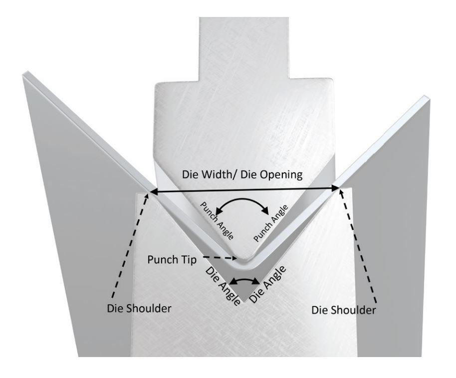
FIGURE 1. In air bending, the die width, not the punch tip, determines the inside bend radius. The radius is “floated” within the die width. Also, the depth of penetration (not the die angle) determines the bend angle in the workpiece.
Our baseline material, low-alloy carbon steel with 60,000-PSI tensile strength, air forms a radius that’s about 16% of the die opening. Percentages vary by material type, yield, temper, and other characteristics. Because of variations in the sheet metal itself, predicting the percentage will never be perfect. Nonetheless, they’re reasonably accurate.
Soft aluminum air forms a radius that’s 13% to 15% of the die opening. Hot-rolled pickled and oiled material air forms a radius that’s 14% to 16% the die opening. Cold-rolled steel (our baseline with 60,000-PSI tensile strength) air forms a radius that’s 15% to 17% the die opening. And 304 stainless steel air forms a radius that’s 20% to 22% the die opening. Again, these percentages have a range of values because of material variations. To find percentages for other materials, you can compare its tensile strength with the 60-KSI tensile strength of our baseline material. For instance, if your material has a 120-KSI tensile strength, the percentage should be 31% to 33%.
Say we have carbon steel with a 60,000-PSI tensile strength, a thickness of 0.062 in., and a called inside bend radius of 0.062 in. Bending it over a 0.472 V-die opening, the resulting formula would look like this:
0.472 × 0.16 = 0.075
So, your inside bend radius will be 0.075 in., a value you can use to calculate the bend allowance, K-factor, setbacks, and bend deduction with some accuracy—that is, if your press brake operators use the correct tooling and engineering designed the part around the tooling the operators use.
In the example, the operator is using a 0.472-in. die opening. The operator walks to the office and says, “Houston, we have a problem. That 0.075-in. punch radius? It seems that we do have a problem; where are we going to get one of those? The closest we can get off the shelf is 0.078 in. or 0.062 in. The 0.078-in. punch radius is too big, and the 0.062-in. punch radius is too small.”
But this is a false choice. Why? The punch radius does not create the inside bend radius. Remember, we are not talking about bottom bending where, yes, the punch nose is the deciding factor. We’re talking about air forming. The width of the die creates the radius; the punch is only the pushing unit. Also note that the angle of the die has no effect on the inside bend radius. You might be using an acute, V, or channel die; if all three have the same die width, you will get the same inside bend radius.
The punch radius plays a role in the results, but it is not the arbiter of the bend radius. Now, if you form with a punch radius that is larger than the floated radius, the part will take on the larger radius. This changes the bend allowance, setbacks, K-factor, and bend deductions. So, that would not be a good choice, right? You got it—it wouldn’t be a good choice.
What if we used a 0.062-in. punch radius? This punch would be a great choice. Why? Because, at least when working with off-the-shelf tooling, it is as close as you can get to the naturally “floated” inside bend radius. Using such a punch nose in this application should give you consistent, stable bends.
It is ideal to choose a punch nose radius that’s close to but does not exceed the floated radius in the part. The smaller the punch nose radius gets in relation to the floated bend radius, the less stable and predictable the bend will become, especially if you end up bending sharp. A punch that’s too narrow will crease the material and create a sharp bend with poor consistency and repeatability.
Material Thickness Factors
Many ask me why the material thickness only comes into play when selecting the die opening. The percentage values used to predict an air-formed radius assume the die being used is of the appropriate die opening for the material thickness. That is, the die opening isn’t larger or smaller than necessary.
While you can form into under- or oversized dies, the radius will tend to distort, thus changing many of the bend function values. You will also see similar effects if you use an incorrect punch radius. So, the rule of thumb about choosing a die opening that’s eight times the material thickness is a good place to start.
The Benefits of Communication
The best-case scenario would be for engineering to go to the shop floor and talk with the press brake operators. Make sure everyone knows the difference between the forming methods. Find out what methods they use and with which materials. Get a list of all of the punches and dies they have available, then design the parts around that information. Next, in the documentation, note the punch and die that will be required for the part to form correctly. Of course, you’ll have extenuating circumstances where you might need to adjust the tooling, but that should be the exception and not the rule.
Operators, I know that you are all prima donnas; I was once one myself! But gone are the days that you can pick a toolset of your liking. Nonetheless, being told which tooling the part was designed to be built with is not a reflection of your skill level. It is merely a fact of life. We air form now; we no longer bottom bend. The rules have changed.
About the Author

About the Publication

subscribe now

The Fabricator is North America's leading magazine for the metal forming and fabricating industry. The magazine delivers the news, technical articles, and case histories that enable fabricators to do their jobs more efficiently. The Fabricator has served the industry since 1970.
start your free subscription- Stay connected from anywhere

Easily access valuable industry resources now with full access to the digital edition of The Fabricator.

Easily access valuable industry resources now with full access to the digital edition of The Welder.

Easily access valuable industry resources now with full access to the digital edition of The Tube and Pipe Journal.

Easily access valuable industry resources now with full access to the digital edition of The Fabricator en Español.
- Podcasting

In this episode of The Fabricator Podcast, Caleb Chamberlain, co-founder and CEO of OSH Cut, discusses his company’s...
- Trending Articles
1
Tips for creating sheet metal tubes with perforations

2
Supporting the metal fabricating industry through FMA

3
JM Steel triples capacity for solar energy projects at Pennsylvania facility

4
Fabricating favorite childhood memories

5
Omco Solar opens second Alabama manufacturing facility
