


Grand unifying theory of press brake bending: Part IV
Tying it all together

For the past few months I’ve detailed a new way of predicting the inside bend radius. Instead of the traditional terms such as radius and profound-radius bends, we’re using some new terminology. I’m calling this the “Grand Unifying Theory” of radius, bend deduction, and die selection, and ultimately it may help you make your bend calculations more accurate than ever.
For this final installment, I’ll review the definitions and bring you through the entire process, from calculating springback to incorporating the bend function calculations. Note that all measurement values—including material thickness, radius, punch nose diameter, and die width—are in inches unless otherwise specified.
The Terms
Types of Bends
Sharp bend: Specified inside bend radius that is generally 63 percent or less of the material thickness of 60-KSI cold-rolled steel. (For more on this, see “How an air bend turns sharp” on www.thefab ricator.com.)
Perfect bend: Specified inside bend radius that’s between 63 percent and 125 percent of the material thickness.
Radius bend: Specified inside bend radius that’s greater than 125 percent of the material thickness.
Bending Methods
Air forming: Three-point bending in which the material contacts the punch nose and the radius of the die shoulders during the forming cycle. The floated inside radius forms as a percentage of the die width.
Bottoming: Forced bends, usually at 90 degrees, with angular clearance between the punch and die; the punch descends until the material wraps around the punch nose, after which the ram continues to apply pressure, forcing material against the die face to the desired bend angle. This produces a radius that’s slightly larger than the punch nose, which is why a springback factor still needs to be taken into account. Bottoming occurs at about 20 percent of the material thickness, as measured from the bottom of the V die.
Coining: Occurs when the tool geometry is stamped into the material at less than the material thickness. It is rarely performed.
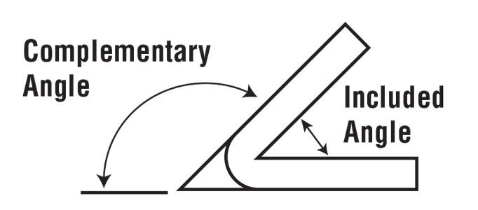
Wiping: Occurs in aircraft tooling during the forming of complementary angles greater than 90 degrees.
Angles
Bend angle: Angle after springback.
Bent-to angle: Angle the press brake overbends to overcome springback.
Included bend angle: Angle of bend as measured between the two legs.
Complementary bend angle: 180 degrees minus the included bend angle.
Sf: Springback factor.
Tooling
Punch: Usually the upper tool, the punch pushes the workpiece into lower die space.
V die: Angles from 85 to 90 degrees included.
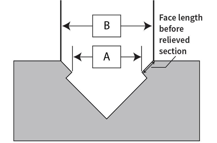
For accurate bend calculations, relieved die widths must be measured by the A dimension.
Acute V die: 30 to 85 degrees included.
Relieved V die: Section of the die faces removed, which allows the punch to overbend for springback without crashing into the die.
Aircraft die: Channel dies in which the depth is 120 percent of the width
Channel die: 180-degree dies that do not maintain the width-to-depth relationships of aircraft dies.
Forming Variables
Mt: Material thickness
Dp: Depth of penetration, the distance the punch tip enters the die space
Ir: Inside bend radius
Rp: Radius of punch tip (Note: Ir and Rp sometimes can be interchangeable)
BA: Bend allowance
BD: Bend deduction
OSSB: Outside setback
The Steps
1. Calculate the springback and estimate the bent-to angle.
This is for air forming. Note that Rp and Mt values are in millimeters. Also note that the results are approximations at best. There are far too many variables to predict springback with total accuracy.
2. Select method: Air forming, air forming with backup, bottoming, wiping (aircraft).
3. Select tooling style and calculate optimal die width.
Air forming with V die and acute V die
Channel die (not aircraft tooling)
Aircraft die
For bend angles less than 90 degrees complementary:
For bend angles greater than 90 degrees complementary:
Note: Aircraft tooling does not allow for sharp or “creased” inside bend radii; therefore, it would be highly uncommon to find tooling used in a sharp bend relationship.
Air forming with relieved V die
Bottoming
The formulas here give you the perfect die width, but that value rarely will match available standard die widths, so you need to choose the closest die width available.
4. Determine the tonnage requirements.
5. Determine where the bend turns sharp.
Minimum force per foot necessary to pierce the material surface, based on 1-to-1 material-thickness-to-inside-bend relationship.
Piercing tonnage should be greater than forming tonnage. The radius on the nose of the tool should be no less than the calculated “sharp” value of the bend.
6. Determine the springback factor.
7. Determine the actual radius
Bottoming
Air forming a sharp bend calculated as a parabola
In the online calculator at http://www.had2know.com/academics/parabola-segment-arc-length-
area.html, “Height” equals outside bend radius and “Width” equals the die width. Or, you can perform the following equation:
Use this “Length of Arc” value, along with the die width (“Width of Arc”), at www.handymath.com’s “Complete Circular Arc Calculator.” The result needed is the “Height of Arc” value. The height of arc from the calculator will serve as our initial value for the outside radius. To obtain our final inside radius:
Air forming a perfect bend, with the radius calculated as a percentage of the die opening
The inside radius is calculated using the 20 percent rule, a label only. The 20 percent rule refers to the floated radius achieved when bending 304 stainless steel, about 20 percent of the die width. Our baseline percentage, for 60-KSI cold-rolled steel, is 16 percent. This is a median value. Over time you may raise or lower the percentage slightly based on how a certain material forms.
Performing a radius bend
If bend angle does not exceed 90 degrees complementary:
If the angle exceeds 90 degrees complementary, you need to account for multibreakage. The larger the radius-to-material thickness, the worse the effect.
Note that this is only an estimate. You may not see this effect in high-tensile-strength material until the bend angle is well past 90 degrees. Nonetheless, the inside radius will get smaller as the included angle gets smaller.
Note that the depth of penetration (Dp) formula below uses the bent-to angle (angle achieved before the bend springs back), not the final bend angle.
Bending in a die backed up with urethane
8.Calculate the bend functions.
In these formulas, Rp (for bottoming) can be replaced with Ir (for air forming).
Note: The OSSB formula can use the included or complementary bend angle, depending on how you run your flat-blank calculations. For more on this, see “The basics of applying bend functions,” available at www.thefabricator.com.
About the Author

About the Publication

subscribe now

The Fabricator is North America's leading magazine for the metal forming and fabricating industry. The magazine delivers the news, technical articles, and case histories that enable fabricators to do their jobs more efficiently. The Fabricator has served the industry since 1970.
start your free subscription- Stay connected from anywhere

Easily access valuable industry resources now with full access to the digital edition of The Fabricator.

Easily access valuable industry resources now with full access to the digital edition of The Welder.

Easily access valuable industry resources now with full access to the digital edition of The Tube and Pipe Journal.

Easily access valuable industry resources now with full access to the digital edition of The Fabricator en Español.
- Podcasting

In this episode of The Fabricator Podcast, Caleb Chamberlain, co-founder and CEO of OSH Cut, discusses his company’s...
- Trending Articles
1
Tips for creating sheet metal tubes with perforations

2
JM Steel triples capacity for solar energy projects at Pennsylvania facility

3
Are two heads better than one in fiber laser cutting?

4
Supporting the metal fabricating industry through FMA

5
Omco Solar opens second Alabama manufacturing facility
