


Predicting an air-formed radius on the press brake, and k-factor research
Metal bending guru Steve Benson works through a backlog of questions
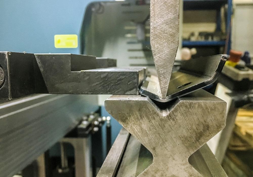
Bending guru Steve Benson works through a backlog of reader questions. This month he covers the k-factor and the role of material thickness when predicting an air-formed radius. Getty Images
The Effect of Material Thickness on an Air-formed Radius
Q: When predicting the inside bend radius, doesn’t the material thickness affect the calculation of the 20% rule? For example, you state that for cold-rolled steel the radius forms to between 15% and 17% of the die opening. If you were to use the same die to form both 18 and 20 ga., wouldn’t the material thickness affect the inside radius?
A: Yes, the material thickness does affect the final inside bend radius, but not dramatically. To review, the final inside radius is calculated based on a percentage of the die opening—that is, the 20% rule. The rule gets its name from the percentages used when air forming stainless steel, which forms a radius between 20% and 22% of the die opening. Cold-rolled steel forms a radius that’s between 15% and 17% of the die opening.
The rule assumes you are using a die opening appropriate for the thickness of the material and the inside bend radius you are trying to achieve. If the die is too small, you will force a smaller radius into the part in much the same way bottoming would, even though you are still technically air forming. If the die is too large, the radius can become a bit distorted.
The 20% rule is only an estimate of the inside bend radius. The most significant variable is the material itself. All materials have a tolerance zone around thickness, yield strength, tensile strength, and other factors, so no two pieces of material are the same. In fact, they can vary within a single sheet.
Material variables are the reason we use a range of percentages, 15% to 17% for cold-rolled steel. If you get your material from the same vendor consistently, you will settle on a percentage that will be reasonably stable as to the variables. If you get your materials from several vendors, the percentages will be all over the map.
Material grain, both natural and finish, is another factor that affects the radius. You’ll get a larger radius forming across the grain and a smaller radius forming with the grain.
In short, pick a die appropriate for the material thickness and inside radius you wish to achieve, or take the die opening that you wish to use without getting too small or too large. The percentage will give you a reasonable inside radius estimate for you to work with when calculating the bend allowance, setback, and the bend deduction. But always remember that, because of material variables, it will only be an estimate of that radius. If you need to be more precise, a test piece is the answer.
A Proof for K-factors?
Q: I am doing some research on sheet metal bending and manufacturing processes, specifically the k-factor corresponding to material thickness. I am trying to find the actual standard (i.e., ANSI, ASME, DIN, or any other professional publication) that identifies this information. Do you know of such a publication? Where is the “proof” behind the tables for k-factor? Thanks for any help you can provide.
A: I have never run across a published proof behind k-factors, only charts and graphs. The “proof” is in the mathematics! This doesn’t mean there aren’t excellent university-level studies out there on k-factors in sheet metal. You can check some of them out at researchgate.net.
There are many ways to calculate a k-factor, and I won’t elaborate on them here. For more on these calculations, see “Analyzing the k-factor in sheet metal bending.” Values from different formulas will vary slightly, and that’s OK. Typically, you’re told what a k-factor is (see Figure 1) and how to calculate it, but rarely where to apply it.
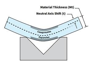
FIGURE 1. The k-factor describes the material’s neutral axis shift during bending.
So, here’s how to apply it. A k-factor of 0.4468 is the one used most often. Let’s say I have a piece of 0.060-in.-thick sheet metal. If I multiply this thickness by my 0.4468 k-factor, I get 0.0268. I subtract this value from my material thickness (0.060 in.) and I get 0.0332. That tells me that the neutral axis has moved from its starting point at 0.030 in. (50% of the material thickness) to 0.0332 in. Subtract this from 0.030 in., and you find that the neutral axis has moved 0.0032 in. from its starting point at 50% of the material thickness. So, how and where do we apply this newly calculated value? We use it to calculate the bend allowance (BA):
BA = {[0.017453 × Inside bend radius] + [(π/180 × k-factor) × Material thickness} × External bend angle
If we insert the common k-factor of 0.4468 into this formula and multiply it by π/180, we get 0.0078, a number you might recognize from the BA formula I’ve given in previous columns. Also note that the BA formula uses the external bend angle, or the angle measured from the outside of the bend (see Figure 2).
Next, determine the outside setback (OSSB). We usually use the external bend angle, but it can be either the internal or external bend angle depending on how you calculate the flat blank:
OSSB = [Tan (Bend angle/2)] × (Material thickness + Inside radius)
We then subtract the BA from double the OSSB to arrive at the bend deduction (BD):
BD = (OSSB × 2) - BA
So, with a 0.060-in. inside bend radius in 0.060-in.-thick material, we would calculate a BA of 0.136, an OSSB of 0.120, which we would double to 0.240 and then subtract 0.136, leaving a BD of 0.104.
The OSSBs will remain constant, but the BA can vary some with slightly different k-factors. In the real world, that slight difference is meaningless with the material thickness tolerance zones most shops work with. For instance, 16-ga. sheet metal can be anywhere between 0.053 and 0.067 in. thick, and a general print tolerance can range from 0.010 to 0.030 in. This is why I believe you’ll find only charts and graphs in the technical literature, no proofs.
As to the 0.4468 value, it represents the average value when we have a one-to-one relationship between the inside radius and material thickness. It’s also the figure shown in the chart in Machinery’s Handbook.
Also note that some calculations can result in a k-factor greater than 50% of the thickness. But in the real world, the k-factor cannot be greater than 50%, because compression on the inside of the bend cannot exceed the expansion on the outside of the bend.
Making Progress
As I noted in last month’s column, I am working my way through a backlog of questions, and there will be more to come. If you have asked me a question and I haven’t answered it yet, with any luck I will cover your question next month.
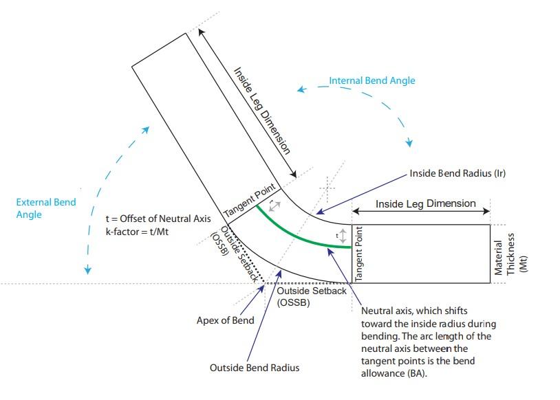
FIGURE 2. Basic bending variables include the bend allowance (BA), which is the arc length of the neutral axis between the tangent points; the outside setback (OSSB); and the bend deduction (BD), which is calculated by doubling the OSSB and subtracting the BA. You use the k-factor—which accounts for the neutral axis’s inward shift—to calculate the BA.
About the Author

About the Publication

subscribe now

The Fabricator is North America's leading magazine for the metal forming and fabricating industry. The magazine delivers the news, technical articles, and case histories that enable fabricators to do their jobs more efficiently. The Fabricator has served the industry since 1970.
start your free subscription- Stay connected from anywhere

Easily access valuable industry resources now with full access to the digital edition of The Fabricator.

Easily access valuable industry resources now with full access to the digital edition of The Welder.

Easily access valuable industry resources now with full access to the digital edition of The Tube and Pipe Journal.

Easily access valuable industry resources now with full access to the digital edition of The Fabricator en Español.
- Podcasting

In this episode of The Fabricator Podcast, Caleb Chamberlain, co-founder and CEO of OSH Cut, discusses his company’s...


