


Graduate Research Associate - Center for Precision Forming
To meet ever-increasing requirements for fuel efficiency and crashworthiness, automakers and their suppliers are working with lighter and higher-strength materials, such as advanced high-strength steels (AHSS) and high-strength aluminum alloys. However, springback in these materials can cause geometric and dimensional inaccuracies in the formed part. To ensure part quality and to compensate for springback, some fabricators are modifying and recutting the automotive dies many times during tryouts.
To help gain an understanding of this springback phenomenon, researchers at the Center for Precision Forming (CPF) at The Ohio State University, in cooperation with Hyson Metal Forming Solutions, Brecksville, Ohio, conducted a study of a relatively simple, 2-D hat-shape bending operation.
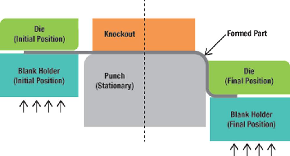
Hat-shape bending (see Figure 1) is a forming operation in which a significant amount of the metal sheet is bent. The material has a natural tendency to unbend itself because of the residual bending stresses created in the side wall of the hat-shaped part. This causes the side wall to curl, causing springback.
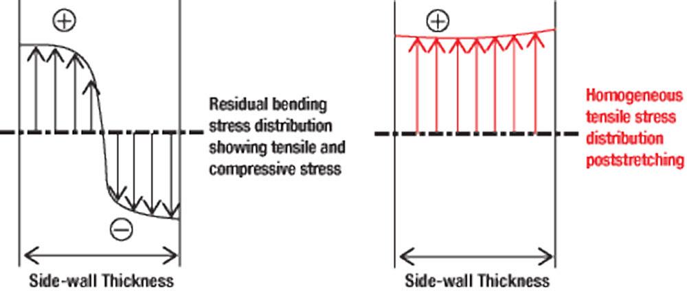
To remove these unwanted stresses in the final formed part, the side wall is made to undergo stretching in the final stages of the forming operation by restraining the material flow. This stretching after bending, called poststretching, eliminates the compressive stresses in the side wall (see Figure 2), thereby reducing springback in the final part.
In this study, researchers used a 300-ton Komatsu servo press and servo-hydraulic cushion, located at Hyson Metal Forming Solutions, to carry out experiments. Servo presses can increase production rates compared to mechanical presses through shorter cycle time (higher strokes per minute), availability of pendulum mode, and reduced stroke length.
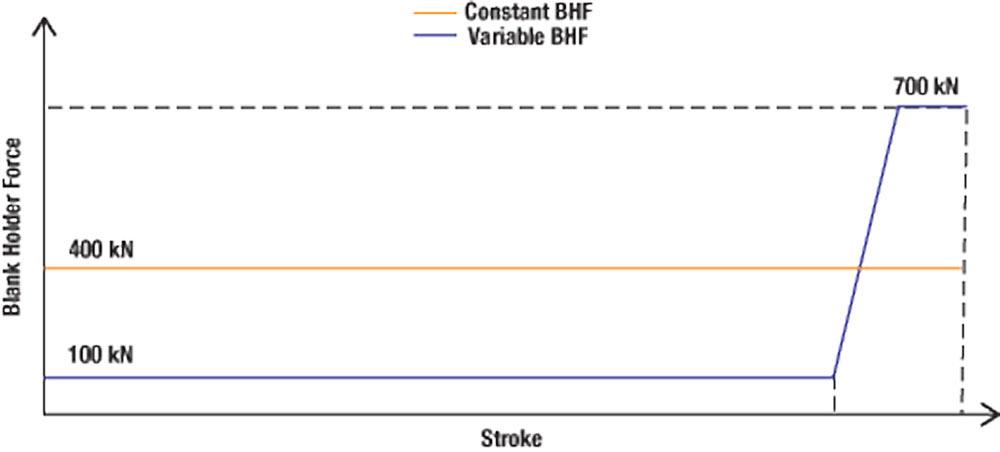
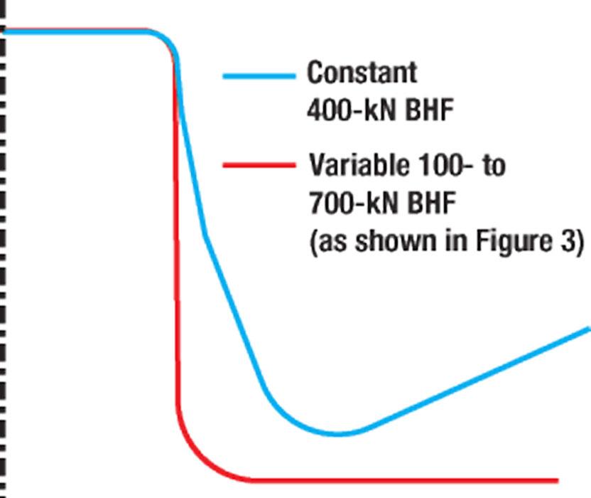
The force required to stretch the blank can be generated by draw beads and pneumatic (air or nitrogen) or hydraulic cushions. In this study, the poststretching was performed using a hydraulic cushion; cushion force was increased toward the end of the forming stroke to induce stretching (see Figure 3). With servo control, the cushion force can be varied during the stroke. Thus, the blank holder force (BHF) can be varied to obtain the optimum metal flow control, based on part geometry and sheet material thickness and properties. Servo-hydraulic cushions allow the operator to change the BHF during the press stroke, within the limits of the hydraulic system’s specific inertia. This level of accuracy is made possible by the closed-loop control inherent in servo-hydraulic cushion systems.
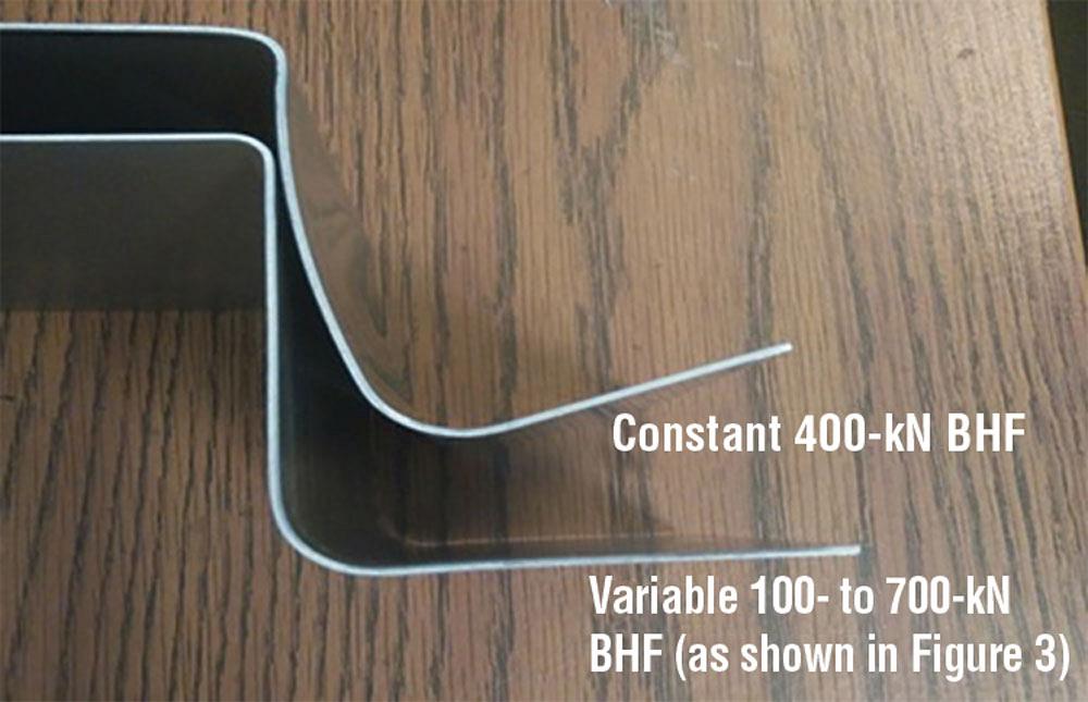
The results, obtained through the finite element (FE) simulations (see Figure 4), show that a variable BHF system can use lower binder forces at the beginning of the stroke to maintain a BHF that allows the material flow into the die cavity. The binder force then is raised at the end of the stroke to obtain the deformation required within the forming limits—for instance, maximum thinning in the part should not exceed the limit value (taken as 15 percent for aluminum). In contrast, using constant BHF results in little springback reduction. FE simulations, performed to mimic the experimental conditions, showed good prediction of the springback results obtained in the experimental setup for Al5182-O (1.2 mm) (see Figure 5).
Studies conducted by the CPF clearly indicate that in addition to part geometry (usually specified by the designer or original equipment manufacturer), the main parameters that affect the magnitude of springback are flow stress and E-modulus, along with the friction conditions present. Estimating the overall coefficient of friction (CoF) can be difficult, but it plays a major role in the prediction of springback through simulations.
CoF in stamping operations can be evaluated using several methods, such as a strip drawing test, twist compression test, or cup drawing test. In this study, however, researchers adopted a relatively simple methodology to evaluate the friction by considering drawing-in of the material between the die and blank holder. Drawing-in of the material is directly related to the friction force present in the flanges, and it decreases with higher friction. Flange lengths of the experimental samples corresponding to each BHF were measured and compared to the flange lengths obtained through FE simulation. The CoF that matches the experimental flange length is considered to be the input in the FE simulations.
In this study, researchers also used the effects of plastic anisotropy and the yield function to predict springback in FE simulation; they were found to have little influence on the final results.

Professor Emeritus and Director - Center for Precision Forming


The Fabricator is North America's leading magazine for the metal forming and fabricating industry. The magazine delivers the news, technical articles, and case histories that enable fabricators to do their jobs more efficiently. The Fabricator has served the industry since 1970.
start your free subscription
Easily access valuable industry resources now with full access to the digital edition of The Fabricator.

Easily access valuable industry resources now with full access to the digital edition of The Welder.

Easily access valuable industry resources now with full access to the digital edition of The Tube and Pipe Journal.

Easily access valuable industry resources now with full access to the digital edition of The Fabricator en Español.
In this episode of The Fabricator Podcast, Caleb Chamberlain, co-founder and CEO of OSH Cut, discusses his company’s...


