


Graduate Research Associate - Center for Precision Forming
Part II of a two-part series discusses the methodology for evaluating the formability of tailor welded blanks using finite element (FE) simulations of plane strain and hydraulic bulge tests. Getty Images
Editor’s note: This is Part II of a two-part series that discusses the methodology for evaluating the formability of tailor welded blanks using finite element (FE) simulations of plane strain and hydraulic bulge tests. Part I discussed evaluating the formability of tailor welded blanks using tensile test experiments and FE simulations.
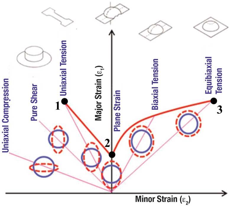
The forming limit diagram (FLD) is the most commonly used failure limit criterion in sheet metal forming to assess formability. A conventional FLD represents the location of the necked or fractured area of sheet metal in a plane of principal strains, ɛ1 − ɛ2, where ɛ1 is the major strain and ɛ2 is the minor strain. The locus of the forming limit, called the forming limit curve, is affected by many factors, such as forming speed, lubricant condition, sheet thickness, strain hardening, and sheet metal anisotropy. Comparing some points in the FLD of monolithic (base) material and tailor welded blanks (TWB) can provide an estimate of the variation in formability (based on the FLD) of TWB as compared to monolithic material (see Figure 1).
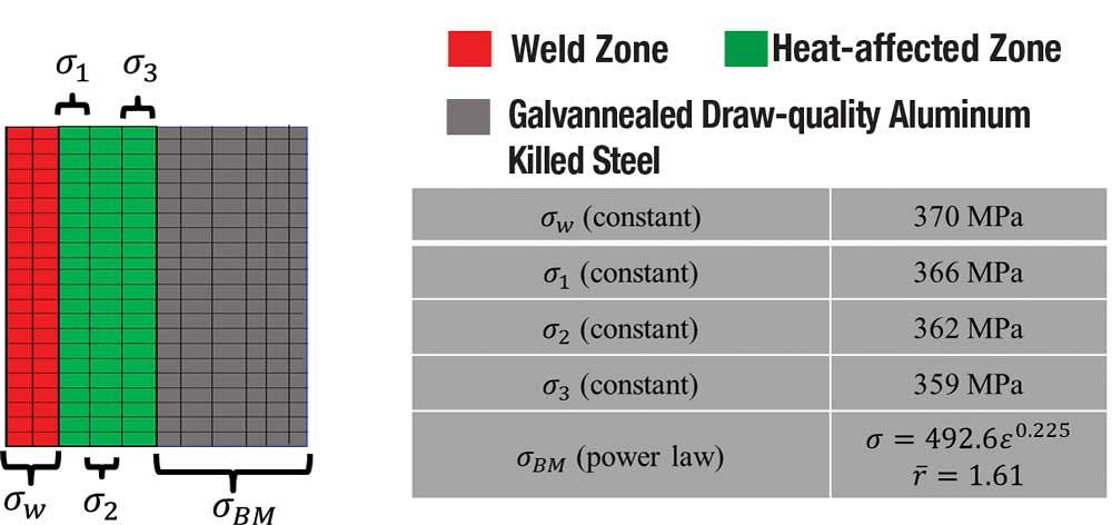
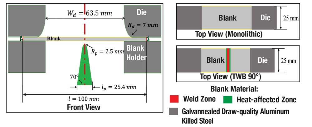
Researchers at The Ohio State University’s Center for Precision Forming conducted a study to determine the variation (from monolithic to TWB) in the major strain (at necking) in plane strain loading (point 2 in Figure 1). They determined the input material parameters for FE simulations of TWB using tensile tests (see Figure 2). The sheet was 1.2 mm thick. To conduct the FE simulations, they used DEFORM-2D software, which uses brick elements. The schematic of the plane strain test setup for FE simulation is shown in Figure 3.
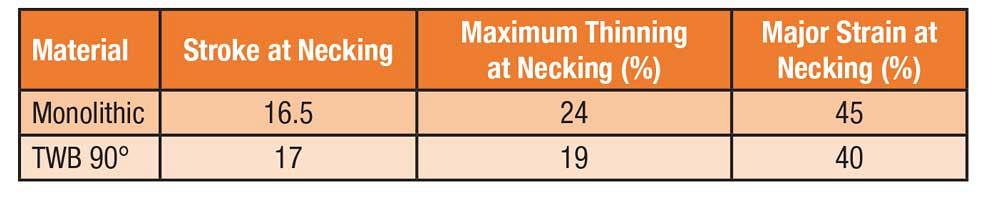
They calculated the variation of maximum thinning with stroke and identified the stroke at necking, in FE simulations, as the stroke at which the thinning increases significantly. The stroke, maximum thinning, and the major strain at necking for monolithic and TWB are shown in Figure 4.
The stroke did not seem to differ significantly, as most of the load in TWB was taken by the base material. Researchers observed a 22% drop in maximum thinning and 11% drop in major strain at necking. The drop in major strain at necking can be visualized as the drop of point 2 in FLD of monolithic material to obtain point 2 in the FLD of TWB.
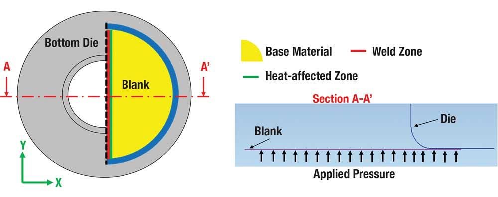
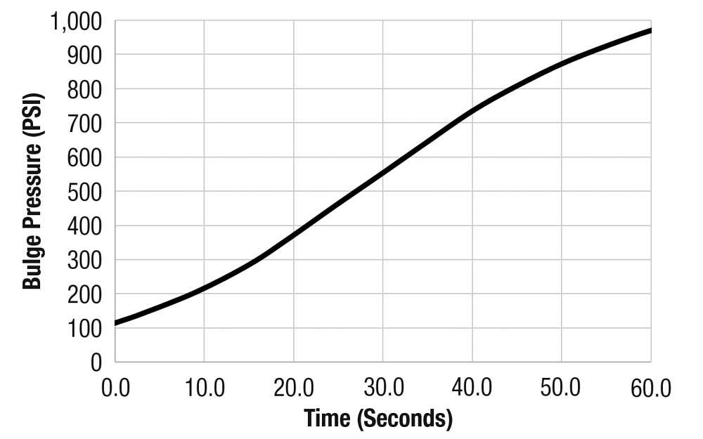
The researchers also conducted a study to determine the variation (from monolithic to TWB) in the major and minor strains (at necking) in biaxial loading (point 3 in the FLD, Figure 1). The input material parameters for FE simulations of TWB are shown in Figure 2. They used PAM-STAMP, which uses shell elements, to conduct the FE simulations of the viscous pressure (hydraulic) bulge (VPB) test (see Figure 5). Bulge pressure as a function of time (see Figure 6) was obtained as an output of VPB test experiments. This variation of bulge pressure with time was used as an input in FE simulations.
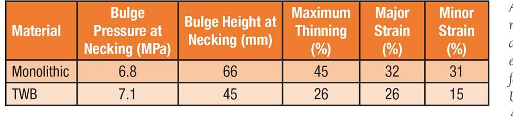
The researchers determined that in FE simulations, the bulge pressure at necking for the VPB test was the bulge pressure at which thinning increases significantly, similar to plane strain. The bulge pressure, bulge height, maximum thinning, and major and minor strains at necking for monolithic and TWB are shown in Figure 7.
The bulge pressure at necking is similar for monolithic and TWB, as most of the deformation occurs in base/monolithic material for TWB, but the bulge height differs significantly, as the harder weld in TWB restricts the increase in height at the center of dome.
Because the weld zone is harder than the base material, there is a significant difference between maximum thinning at necking for monolithic and TWB. In monolithic material, maximum thinning is at the center of dome; in TWB, it is in the base material, adjacent to the heat-affected zone.
The major and minor strains for monolithic material are similar at necking, which implies a biaxial loading condition. The minor strain at necking is significantly lower than major strain at necking for TWB, which implies that the VPB test for TWB is more like a plane strain loading. Therefore, the reduction from monolithic to TWB is more significant in minor strain (about 50%) than in major strain (about 19%). These results suggest that the drop from monolithic to TWB of point 3 in FLD (see Figure 1) cannot be determined using existing biaxial loading tests. Thus, to investigate the behavior of TWB in biaxial loading, a new test needs to be devised.

References
S.K. Paul, G. Manikandan, and R.K. Verma, “Prediction of entire forming limit diagram from simple tensile material properties,” The Journal of Strain Analysis for Engineering Design, Vol. 48, No. 6 (2013), pp. 386-394.
M.R. Tharrett and T.B. Stoughton, “Stretch-bend forming limits of 1008 AK steel,” SAE technical paper No. 2003-01-1157, 2013.


Professor Emeritus and Director - Center for Precision Forming


The Fabricator is North America's leading magazine for the metal forming and fabricating industry. The magazine delivers the news, technical articles, and case histories that enable fabricators to do their jobs more efficiently. The Fabricator has served the industry since 1970.
start your free subscription
Easily access valuable industry resources now with full access to the digital edition of The Fabricator.

Easily access valuable industry resources now with full access to the digital edition of The Welder.

Easily access valuable industry resources now with full access to the digital edition of The Tube and Pipe Journal.

Easily access valuable industry resources now with full access to the digital edition of The Fabricator en Español.
In this episode of The Fabricator Podcast, Caleb Chamberlain, co-founder and CEO of OSH Cut, discusses his company’s...


