


Graduate Research Associate
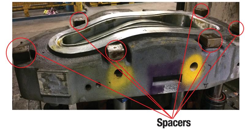
In deep drawing, a flat blank is constrained by a blank holder, while the central portion of the sheet is pushed into a die opening with a punch to draw the metal into the desired shape without causing wrinkles or splits in the drawn part. Large parts, such as automotive doors and hoods, are drawn using draw beads and spacers (or standoffs) to control metal flow into the die cavity (see Figure 1).
Spacers, which are usually 10 or 15 percent thicker than the blank, are used to ensure that the die halves close in a parallel fashion, which then compensates for elastic deformations that may occur in the dies and press bed. Shims increase or decrease the height of the spacers during die tryout and in production to ensure appropriate metal flow and to eliminate wrinkles at desired locations in the die.
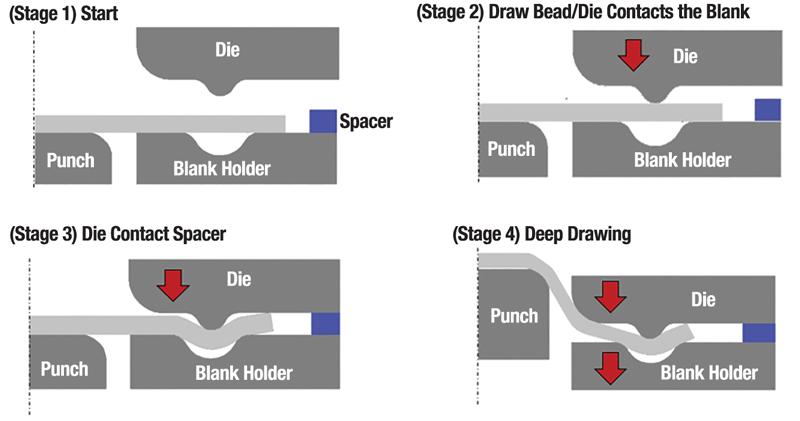
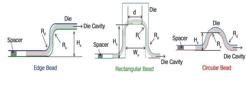
By restraining the metal flow, draw beads reduce the required amount of blank holder force (BHF) that usually is exerted by an air cushion, nitrogen cylinders, or a hydraulic cushion (see Figure 2). Several types of draw beads are commonly used (see Figure 3), and their dimensions depend on the sheet material strength and thickness and the press capacity. When draw beads are in use, the BHF must remain sufficient to keep the die and spacers in contact throughout the forming operation.
When spacers are used, the die and blank holder are pressed against the spacers. At the start of the stroke, the blank is free to flow into the die cavity with the relative movement of the punch against the die. As deformation and punch stroke proceed, the edges of the blank become thicker at the corners of the part, and some minor wrinkling may occur in the flange region. The blank thickness and wrinkle height increase but cannot exceed the clearance between the die and blank holder, provided by the spacers, if the BHF is sufficiently large. At this stage in drawing, the blank holder controls the material flow. The force exerted by the deforming blank upon the die and blank holder increases, while the contact among the die, blank holder, and spacers is maintained.
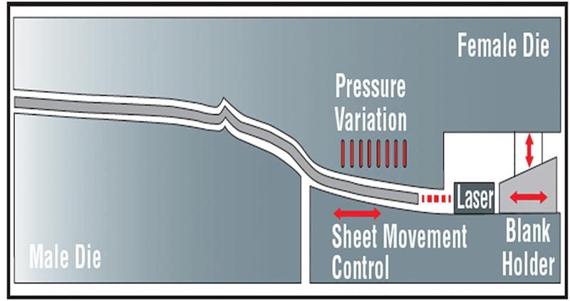
The heights and locations of the spacers usually are determined during tryout through several trial-and-error stampings. Recently Audi developed a laser sensor that measures the flange draw-in (see Figure 4). A control algorithm and a small servomotor activate an adjustable spacer to the optimal value. Called the Intelligent Tool, the laser sensor now is used in production at Audi.
Deep drawing of small to medium-size parts in transfer and progressive dies is accomplished without draw beads and spacers. Progressive dies perform a series of operations at several stations during each press stroke, shaping the workpiece as the strip moves through the die, with the partially formed parts transported by the strip. Metal flow from the flange into the die cavity is controlled by the pressure applied on the flange of the die, usually with mechanical or elastomer springs or nitrogen cylinders.
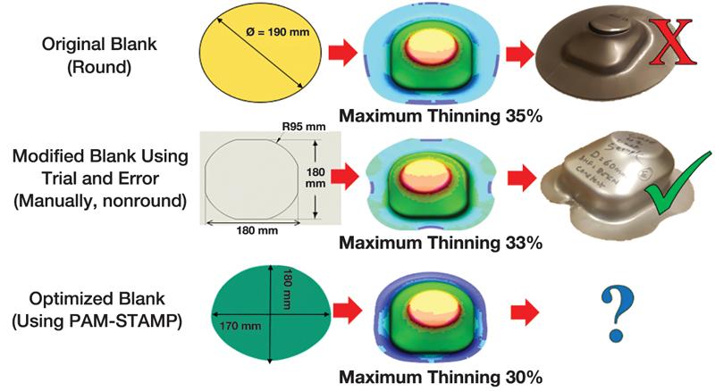
Whether or not draw beads are used in stamping, blank shape optimization is important (see Figure 5). The optimum blank shape can be determined with process simulation, using conventional codes such as PAM-STAMP.

Professor Emeritus and Director - Center for Precision Forming


The Fabricator is North America's leading magazine for the metal forming and fabricating industry. The magazine delivers the news, technical articles, and case histories that enable fabricators to do their jobs more efficiently. The Fabricator has served the industry since 1970.
start your free subscription
Easily access valuable industry resources now with full access to the digital edition of The Fabricator.

Easily access valuable industry resources now with full access to the digital edition of The Welder.

Easily access valuable industry resources now with full access to the digital edition of The Tube and Pipe Journal.

Easily access valuable industry resources now with full access to the digital edition of The Fabricator en Español.
In this episode of The Fabricator Podcast, Caleb Chamberlain, co-founder and CEO of OSH Cut, discusses his company’s...


