


Servo Press Scientist

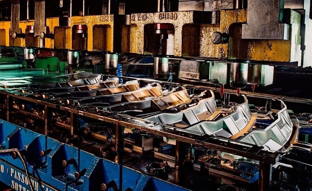
Off-center loading can cause increased press and die wear and maintenance, leading to decreased part quality and more downtime, so predicting it is key. Getty Images
Editor’s Note: This is Part I of a two-part article. Part II will include a case study on predicting off-center loading in multiple operations or in a transfer die.
Off-center loading occurs when the center of the forming load deviates from the press center, leading to a net moment that can produce elastic deflections on the press (see Figure 1) and horizontal forces on the press and tool guides. When this happens, die set tolerances might vary, which can be critical, especially in trimming, blanking, and piercing operations. Small elastic deflections of the press can go unnoticed on the shop floor during day-to-day operations, but they cause increased press and die wear and maintenance, leading to decreased part quality and more downtime.
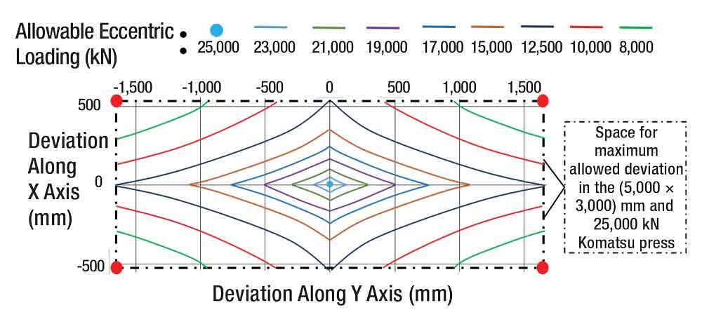
In addition, as the center of load deviates from the press center (see Figure 2), the effective press capacity decreases, which sometimes can cause the available force to be insufficient for forming operations.
For these reasons, it’s important to predict off-center loading accurately.
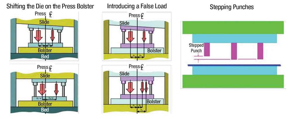
Three methods used to compensate for off-center loading are (see Figure 3):
The aim of this case study was to develop a methodology for predicting the off-center loading in a single die using commercially available finite element (FE) software (in this case, PAMSTAMP). It used a drawn part made of 1.2-mm Al 5182-O that emulated an inner door panel.
The total forming stroke was 156 mm (assuming no fracture of material), and a constant blank holder force of 500 kN was applied throughout the stroke.
Because of the part’s asymmetry, the center of loading (location of the net forming force) shifted within the stroke. Therefore, the net moment on the press (trying to tilt the press bolster) also changed with the press stroke.
Researchers used the following methodology to predict the off-center loading:
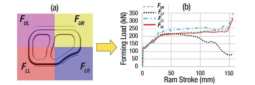
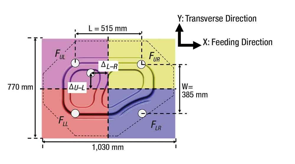
1. Divide the die into four sections (see Figure 4a). The accuracy of off-center loading increased with an increasing number of sections, used for calculations.

2. Calculate the forming load versus stroke curve for each section of the die (see Figure 4b). For a pre-existing die, the forces could also be measured during tryouts by installing load sensors in the columns of the press (known distance from the press center). The differences (unbalances) in load at each section of the die created a net moment in the press.
3. Assume the center of load for each die section (FUL, FUR, FLL, and FLR) to be at its geometrical center. To calculate the variation of the location of off-center load with stroke, they obtained this location for each ram position (see Figure 5) using the following formulas:
Considering: ΔL-R = My/Fz ; ΔU-L = Mx/Fz
Off-center load distance along transverse direction (ΔL-R) = L(FUR+FLR-FUL-FLL)/2(FUR+FLR+FUL+FLL)
Off-center load distance along feeding direction (ΔU-L) = W(FUR+FUL-FLL-FLR)/2(FUR+FLR+FUL+FLL)
Where:
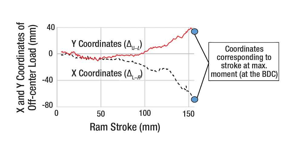
As the location of off-center load changes with the stroke (see Figure 6), the net moment (due to off-center loading) on the press can be minimized but not eliminated.
4. Shift the die in the press so that the press center coincides with the coordinates of the maximum moment (see Figure 6).
In this case study, the maximum moment about the X axis decreased at least 50 percent after forming the part with the die adjusted in the press. While other methods can be used to compensate for off-center loading, the method used depends on the press restrictions, such as space availability and loading capacity.
Steps 1 through 3 of this methodology have been integrated into AutoForm R8 2019 software. This software provides variation of net force on the die and its location with respect to ram stroke, which the researchers used for the simulations to be discussed in Part II of this article.
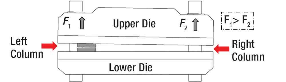
Figure 1
This schematic representation shows elastic deflection in a press due to net moment caused by off-center loading. Courtesy of AIDA Tech.
Reference:
D. Boerger, “Off-Center Loading in Multi-Stage Tooling,” Appliance Manufacturer, Vol. 49, No. 9 (2000), p. 29.


Professor Emeritus and Director - Center for Precision Forming


The Fabricator is North America's leading magazine for the metal forming and fabricating industry. The magazine delivers the news, technical articles, and case histories that enable fabricators to do their jobs more efficiently. The Fabricator has served the industry since 1970.
start your free subscription
Easily access valuable industry resources now with full access to the digital edition of The Fabricator.

Easily access valuable industry resources now with full access to the digital edition of The Welder.

Easily access valuable industry resources now with full access to the digital edition of The Tube and Pipe Journal.

Easily access valuable industry resources now with full access to the digital edition of The Fabricator en Español.
In this episode of The Fabricator Podcast, Caleb Chamberlain, co-founder and CEO of OSH Cut, discusses his company’s...


