


Contributing Writer

Editor’s Note: This is the sixth in a series of articles presenting the fundamentals of stamping die design and construction.
To make a part geometry that is tall, you have to get the metal to flow inward. The only way metal will flow is if you limit the amount of material around the perimeter of the draw punch. And minimization of the material surrounding each punch must be performed in steps, with each step resulting in a punch that is smaller in diameter and taller than the previous one.
Fundamentally, the concept is to gather the surface area that you need to make the final product in the first drawing station and gradually displace the same surface area into a geometry that is smaller in diameter and taller. This is the basic concept of a draw reduction.
To determine the blank size, you first must determine the height of the final part, then add more material that will later be trimmed off. This extra material is called engineered scrap. For example, if you are attempting to make a round cup that is 1 in. dia. and 4 in. tall, you will need to trim it to exactly 4 in. tall after forming it, so the final height of the formed part will need to be a little more than 4 in. Adding two times the metal thickness as extra trimming material is good practice. In other words, if the 4-in.-tall cup is being made from 0.010-in.-thick steel, the final height of the finished drawn shell should be 4.100 in.
By calculating the surface area of a can that is 1 in. dia. and 4.100 in. tall, you can mathematically determine the blank size. The equation in Figure 1 will give you a rough blank diameter, but note that it does not consider the radius at the top of the cup.
So, in this example, a 4.1-in.-tall and 1-in.-dia. cup would require a blank that is approximately 4.171 in. dia.
To find the number of drawing stations required for the operation, you’ll need a draw reduction chart (see Figure 2). This chart contains mathematical values based on draw ratio theory—the relationship between the size of the blank and the size of the punch. Many companies have developed their own, often proprietary, draw reduction values based on their experience and their niche.
The numerical values in this chart change significantly with respect to the metal type and thickness. As a general rule, thinner materials require more operations (reductions) than thicker materials.
The first drawing station, known as the cupping station, transforms the circular blank into a round cup. The fundamental concept behind the first drawing operation is to obtain the amount of material necessary to make the final geometry. Each drawing station is thus related and must follow draw ratio theory.
For the original cup design of 1 in. dia. and 4.1 in. tall, after calculating the surface area, you mathematically determined that the required blank size is 4.171 in. dia.
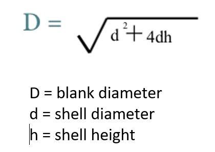
FIGURE 1. This equation provides a rough blank diameter, but note that it does not consider the radius at the top of the cup.
By referencing the draw reduction chart, you can determine that the blank can only be reduced by 40% in the first drawing or cupping operation. This essentially means that the draw punch must be at least 60% of the blank diameter—a calculation commonly referred to as the inverse value. Noted in red on the reduction chart shown in Figure 2, the inverse value helps to simplify the mathematical calculations. For example, if you choose to use the reduction percentage of 40% instead of the inverse value, the calculation for the first draw punch diameter is:
40% x 4.171 in. = 1.669 in.
4.171 - 1.669 in. = 2.502 in.
Using the inverse value of 60%, the calculation is simpler:
60% x 4.171 in. = 2.502 in.
So, to keep an acceptable drawing ratio, the first draw punch (cup) must be greater than or equal to 2.502 in. dia.
Because the first cupping operation is larger than the finished cup diameter, more reductions will be required. Using the inverse values shown in the reduction chart in Figure 2, you can calculate each of the subsequent drawing stations:
Because 0.971 in. is smaller than the finished cup diameter, six drawing stations will likely be required to make this geometry. Keep in mind that each end value is a minimum diameter; the punch can always be larger but typically not smaller than the calculated value. Depending on the ductility and thickness of the material, more or fewer operations might be needed.
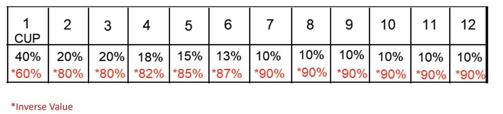
FIGURE 2. A draw reduction chart contains mathematical values based on draw ratio theory—the relationship between the size of the blank and the size of the punch.


The Fabricator is North America's leading magazine for the metal forming and fabricating industry. The magazine delivers the news, technical articles, and case histories that enable fabricators to do their jobs more efficiently. The Fabricator has served the industry since 1970.
start your free subscription
Easily access valuable industry resources now with full access to the digital edition of The Fabricator.

Easily access valuable industry resources now with full access to the digital edition of The Welder.

Easily access valuable industry resources now with full access to the digital edition of The Tube and Pipe Journal.

Easily access valuable industry resources now with full access to the digital edition of The Fabricator en Español.
In this episode of The Fabricator Podcast, Caleb Chamberlain, co-founder and CEO of OSH Cut, discusses his company’s...


