


Taking a deep dive into press brake tonnage, Part I: Improving formulas
Where do tonnage formulas come from, and how can press brake operators improve upon them?
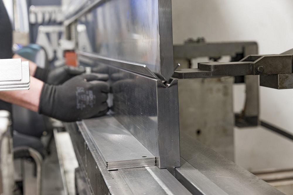
Taking a deep dive into press brake tonnage: Why do bends turn sharp when they do? It has to do with how bending forces affect the workpiece. Getty Images
Over the years I’ve discussed how sharp bends affect bending at the press brake. In that time I have had several questions about why I used 63 percent of the material thickness as the average starting point in mild cold-rolled steel. That is, when the inside bend radius decreases to about 63 percent of the material thickness, the bend “turns sharp” as the punch tip starts to penetrate and crease the bend.
I’ve spent the last year studying the topic, discussing it with some of the smartest and most knowledgeable people I know in the industry. With some confidence, I can explain the precise value where a sharp bend occurs in each type of material.
We’ll cover the details of the sharp bend next month. But to really understand why these sharp bend calculations work, we need to have a deep understanding of how tonnage is calculated in forming.
The Air Bend Force Chart
When air bending, you can refer to a tonnage or force chart, usually with a material gauge on the vertical axis and V-die width on the horizontal axis. Note that the forming force values in these charts are based on specific die width-to-material-thickness ratios (or die ratios), such as the following, with material thicknesses to the left of the equal sign and die ratios to the right:
0.078 in. = Die width 6x material thickness
0.118 in. = Die width 8x material thickness
0.354 in. = Die width 10x material thickness
0.551 in. = Die width 12x material thickness
This is just an example of die ratios from one chart; other charts might be based on different die ratios, and it’s usually notated on the chart itself. Regardless what the die ratios are, pay attention to them (see Figure 1). If your die widths aren’t even close to this, your tonnage calculation from the chart will be entirely inaccurate.
When you find the force figure, you then plug it into a formula that accompanies the chart or otherwise published by the press brake manufacturer, tooling vendor, or material supplier. These formulas use a multiplier value that might be higher or lower depending on the material type you’re working with— a fudge factor, if you will. The higher a material’s tensile strength, the larger the tonnage multiplier, a practice that’s consistent with most forming tonnage formulas used throughout the industry.
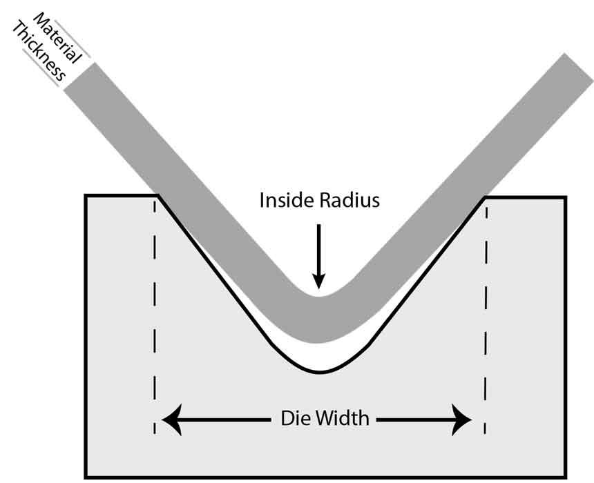
Figure 1 The die ratio is the die width divided by the material thickness. The greater the ratio, the less bending force an application requires.
For many years I have used the following formula to calculate the forming force that would be required to complete a bend:
Forming tonnage per inch =
(575 × Material thickness2)/Die opening/12
From there, the answer would be factored for material type, length of bend, and method of forming. This formula works rather well for the middle-of-the-road materials like AISI 1015 steel with 60,000 PSI tensile strength—our baseline value.
Of course, plenty of other tonnage formulas exist. Consider the following:
P=(b×t2×Rm)/[(W–Rd–Rp)×9,800]
Where:
P = Required force, metric tons
t = Material thickness
W = Die width, mm
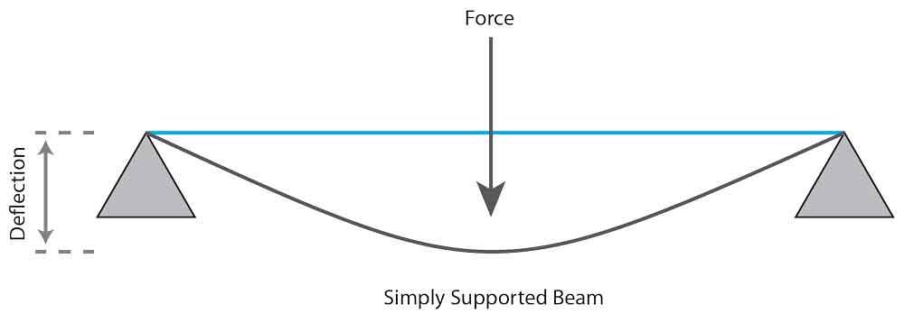
Figure 2 Some of the industry’s tonnage calculations have their origins in the construction industry, including simple beam theory.
b = Bend length, mm
Rm = Tensile strength, MPa
Rd = Die entry radius
Rp = Punch radius
This tonnage equation (found in literature from both SSAB and Pacific Press) includes the die radius (Rd), which, as we will see, can affect bending force significantly. That said, it doesn’t seem to work well when applied to the middle and softer ranges of material.
Intro to Beam Theory
Where did the formula originate? More specifically, where did the 575 value come from, and what does that value represent? In a previous column I stated that I was unable to determine the origin of the formula or where the 575 value came from. I guessed it dated back to the 1950s and was probably from the construction industry. While I still do not have definitive proof of the origin of this formula, the formula itself does seem to be based on simple beam theory.
When we bend sheet or plate, it is no more than a supported beam spanning across two points, the top shoulders of a V die, with a concentrated load in the middle created by the descending nose of the punch (see Figure 2). The length of the “beam” is equal to the width of the press brake die opening, and the load is equal to the force exerted on the plate by the ram and punch.
Beam theory gives us a hint—albeit only a possible hint—about where that 575 comes from in the tonnage formula. If you’re interested in delving into the formulas, check them out in the sidebar.
Why Not Yield Strength?
Traditional tonnage formulas use material tensile strength, not yield strength. But why is this, exactly? After all, isn’t bending rooted in the practice of material “yielding” to forming pressure?
The reason for using the tensile strength, or ultimate tensile strength (UTS), is the consistency of values. Consider Figure 3 and compare the yield strength numbers to those of tensile strength. While the tensile strength climbs consistently, the values for yield strength are all over the map, making those values hard to use in any rational manner.
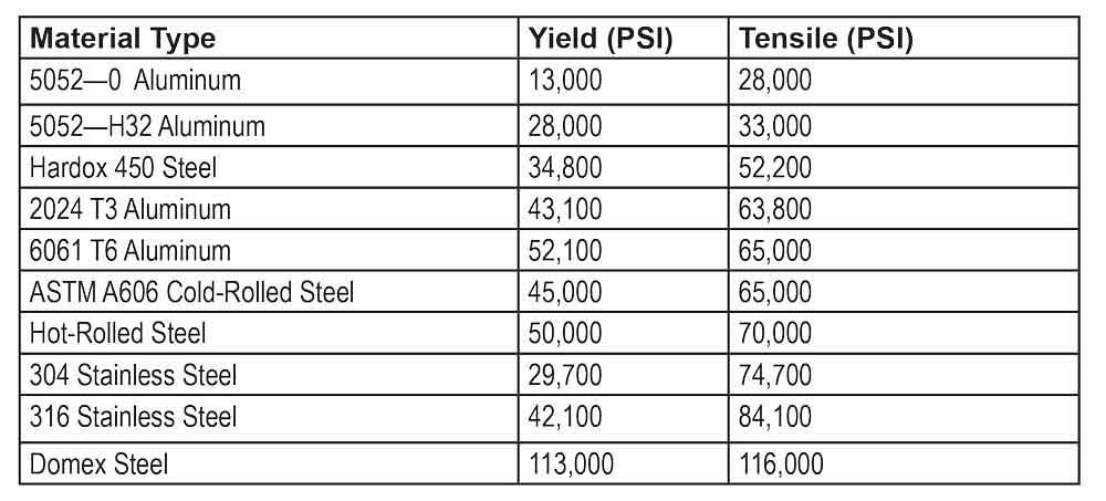
Figure 3 Tensile strength tends to rise consistently among material grades, but the same can’t be said for yield strength. It’s one reason most tonnage formulas use tensile strength and not yield strength.
Some formulas do use yield strength, and some of them are rooted in formulas for calculating the bending moment in a supported beam. Again, if you’d like a taste, check out the sidebar.
The Die Effect: Width and Shoulders
As a die opening gets smaller in relation to the material thickness and inside radius, the more force it takes to bend the part. Similarly, the greater the required tonnage to form, the more friction there is between the material and the die radius. Similarly again, the larger the die ratio, the smaller the tonnage load.
Your machine, be it mechanically, hydraulically, or electrically driven, is designed to bend to a rated capacity. That capacity is calculated where the die ratio is 8-to-1 and you have a “perfect” bending relationship, where the material thickness equals the inside bend radius.
The die ratio for thinner materials can be reduced to 6-to-1, and if you are forming thicker materials, you might have to increase your die ratio to 10-to-1 or 12-to-1 to reduce the bending force and keep the application within the capacity of the press brake.
The radii on the die shoulders (the die radius) also influences force requirements. The smaller the die radius, the higher the force necessary to bend the material. For example, a 0.196-in. die radius will require more bending force than a 0.314-in. die radius.
The smaller die radius also dramatically increases the two die radii’s asperity, or unevenness of surface roughness. The rougher the surface, the greater the bending force required. This also causes greater plastic deformation in the sheet.
The Effects of Friction
With air forming, the V die effectively performs both rolling and sliding. As the sheet rotates into the die, you have rolling; as the punch descends, it drags the sheet over the die radius, and you get sliding (see Figure 4).
This sliding and rolling motion during forming is a function of punch displacement, or the depth of penetration into the die opening. It is also time-dependent. The time component is a function of velocity (bending speed), the displacement between the point of contact (pinch point), and the distance penetrated into the die opening.
The coefficient of friction also will change when you use surface films or lubricants. If the surface of the metal is clean and not lubricated, the friction will be higher, increasing the chance for seizing and material galling, and increasing the required forming force. Reduce the friction and you’ll decrease the chance of seizing and galling, but you’ll also increase the amount of springback in the material.
If no lubrication is present, like urethane sheets or other types of lubricant, the friction between the die and the sheet is controlled by friction adhesion. This will cause a noticeable increase in the friction occurring between the die and material, creating less material springback and requiring more force to bend the part. The materials being bent and the tooling material also play a role. Friction also can contribute to increased tensile stress and outside surface cracking.
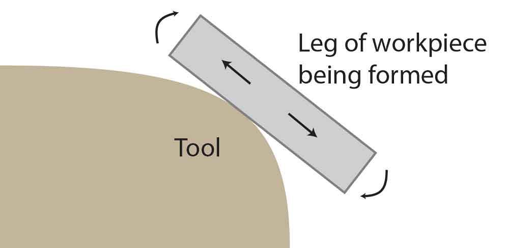
Figure 4 When the bend forms in the die, both rolling and sliding occur. The material 'rolls' as it rotates over the die radius and 'slides' as the punch pushes the material into the die space.
The bending speed, or punch velocity, also influences the required bending force. As forming speed increases, the bending force decreases. The friction coefficient varies with the sliding velocity of the material, and that sliding velocity is proportional to the bending speed. Increasing sliding velocity during bending reduces the friction coefficient and bending force, but at the same time increases material springback.
Sheets with a rough surface texture create more friction and, hence, a greater required bending force. Sheets with heavy surface roughness will exhibit a considerable amount of friction because of an increase in asperity. And bends with increased asperity require a larger bending force and will produce less springback. That said, the die radius and punch velocity play more significant roles when it comes to friction.
Grain Direction
A material’s grain direction in relation to the bend line also affects the required forming tonnage. Ideally, the part should be bent transverse (across) the natural grain direction, or the direction of roll.
Materials with a grain direction are subject to what’s known as anisotropy. Change the bend line’s relationship to the natural grain direction (see Figure 5) and you change the bending results, including the bend angle, springback, and inside bend radius. If you bend across the grain, you’ll achieve a stronger bend that can accept a smaller inside bend radius.
That said, bending with the grain can reduce tonnage requirements. You sometimes can reduce the tonnage requirements by as much as 15 percent by bending with the grain, and by up to 7 percent when bending diagonal (45 degrees) to the grain.
The Tensile Ratio
As you might have guessed by now, I’ve spent quite a bit of time digging around and working with tonnage formulas. There are plenty to choose from besides the ones discussed here. Unfortunately, while there are many ways to calculate tonnage, they all use an approximation, or fudge factor.
Predicting tonnage is never going to be a perfect science. However, we can calculate a reasonably accurate answer as to how much force will be required in a given situation. Rather than using a fudge factor, we can use the tensile ratio. That is, we simply divide the tensile strength of the material at hand by the tensile strength of our baseline A36 steel, 60,000 PSI.
Forming tonnage per inch =
[(575 × Material thickness2) / Die opening / 12]
x (Material tensile strength in PSI / 60,000)
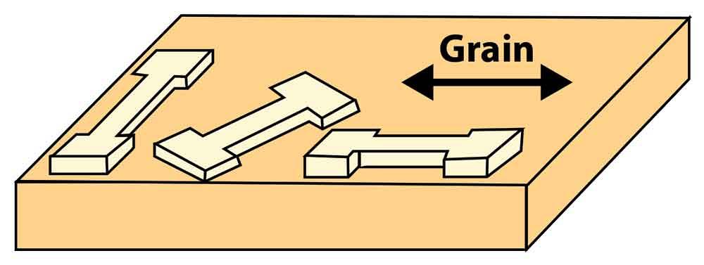
Figure 5 Anisotropic behavior means the bending results change with their relationship to the grain direction.
That last part of the equation (the material tensile in PSI divided by 60,000) is the tensile ratio. Here are some tonnage ratio examples:
Domex, 116,000 PSI tensile:
116,000 / 60,000 = 1.933 tensile ratio
304 Stainless, 74,770 PSI tensile:
74,770 / 60,000 = 1.246
5052 H32 Aluminum, 33,000 PSI tensile:
33,000 / 60,000 = 0.550
5052-0 Aluminum, 28,000 PSI tensile:
28,000 / 60,000 = 0.466
The tensile ratio works with other tonnage formulas too. Take the tonnage value from the calculation method of your choice and multiply it by the appropriate tensile ratio to get the tonnage force value.
Machine Capacity Versus Forming Tonnage
Many things influence the bending force: kinetic friction between the material and the die, material thickness and strength (and variations in both), the rolling direction of the sheet, and work hardening, among other factors. Whether you look at the tonnage force chart or calculate the numbers yourself, those values represent the estimated tonnage to bend material in a given die opening.
The bending force is not the same thing as machine capacity. A machine’s tonnage capacity should exceed an application’s bending force value by at least 20 percent.
Here again, you can use the tonnage ratio. Divide your material’s tensile by the 60,000-PSI baseline, then multiply the tensile ratio by the mild steel capacity value of your press brake. This will give your machine’s capacity for bending the specific material you need to bend.
All this boils down to there being multiple ways to estimate the amount of force required for a piece of sheet or plate to be bent. Some formulas are better than others, depending on the circumstances, but various options will work. Whatever method you choose, never exceed the tonnage capacity of your machine and tooling. Doing so can destroy your brake and, even worse, put your operator in an extremely dangerous situation.
Beam Theory, Adapted for Bending
Most tonnage formulas use tensile strength, not yield strength, simply because yield strength tends to vary. If you change material grades and the tensile strength rises by a certain amount, chances are the yield strength will not increase by the same amount.
That said, it is possible to use material yield in tonnage calculations if we adapt some formulas from the construction industry. They initially were written to describe the bending moment induced in a supported rectangular beam, with a load in the middle.
The following formula adaptations are based on the maximum force needed to bend material to an internal angle of 120 degrees. They also assume a standard amount of friction, or drag, during bending. To adapt these formulas correctly, the die opening is assumed to be as close to geometrically perfect as possible. As the die opening gets smaller in relation to the material thickness and inside radius, the more force it takes to bend the part, and the higher amount of friction you have between the material and die radius.
With all this in mind, we can use the following formulas from beam theory to calculate the force required for a bend.v
M = Bending moment (in.-lbs.)
W = Span length (Die width, in.)
P = Force exerted (lbs.)
Fy = Bending stress = Yield stress of material (PSI)
Z = Plastic section modulus (in.3) = b × t2/2
b = Beam width (Bend length, in.)
t = Beam thickness (Material thickness, in.)
M = P × W/4
Fy = M/Zv
P (lbs.) = 2 × b × t2 × Fy/W
P, expressed in tons per foot = (24/2,000) × t2 × Fy/W
This simplifies to:
P, expressed in tons per foot = 0.012 × t2 × Fy/W
P, expressed in tons per foot, with Fy in KSI = 12 × t2 × Fy/W
That 575 figure might play a role in beam theory too, and it hints at a possible history behind that mathematical constant we use in our common tonnage formulas. Dividing 575 by 0.012 and we get 47,916 PSI, a reasonable yield strength for our 60,000-PSI-tensile baseline material. Know that this is only a possible explanation of the 575 constant’s origin, but it’s an intriguing one.
Steve Benson is a member and former chair of the Precision Sheet Metal Technology Council of the Fabricators & Manufacturers Association International. He is the president of ASMA LLC, steve@theartofpressbrake.com. Benson also conducts FMA’s Precision Press Brake Certificate Program, which is held at locations across the country. For more information, visit fmanet.org/training, or call 888-394-4362. The author’s latest book, Bending Basics, is now available at the FMA bookstore, fmanet.org/store.
About the Author

About the Publication
subscribe now

The Fabricator is North America's leading magazine for the metal forming and fabricating industry. The magazine delivers the news, technical articles, and case histories that enable fabricators to do their jobs more efficiently. The Fabricator has served the industry since 1970.
start your free subscription- Stay connected from anywhere

Easily access valuable industry resources now with full access to the digital edition of The Fabricator.

Easily access valuable industry resources now with full access to the digital edition of The Welder.

Easily access valuable industry resources now with full access to the digital edition of The Tube and Pipe Journal.

Easily access valuable industry resources now with full access to the digital edition of The Fabricator en Español.
- Podcasting

In this episode of The Fabricator Podcast, Caleb Chamberlain, co-founder and CEO of OSH Cut, discusses his company’s...
- Trending Articles
1
Tips for creating sheet metal tubes with perforations

2
Supporting the metal fabricating industry through FMA

3
JM Steel triples capacity for solar energy projects at Pennsylvania facility

4
Are two heads better than one in fiber laser cutting?

5
Fabricating favorite childhood memories
