


Yield, tensile, and bending small metal parts on the press brake
Questions about sheet metal forming terminology and bending tiny parts
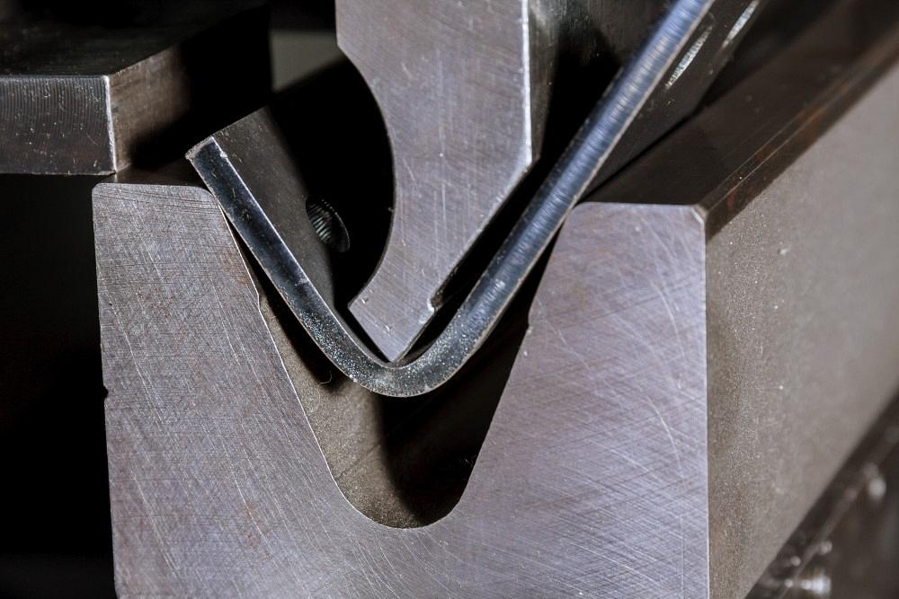
ZhakYaroslavPhoto / iStock / Getty Images Plus
This month, we hear from two read readers, one with a question about terminology, another about bending extremely small parts. One emphasizes how important it is for everyone in the trade to use the same terms. Many use terms interchangeably when, in truth, they’re not interchangeable. The other shows that, while those in the bending trade work by the same fundamentals, they still have plenty of chances to get creative.
Strength Terminology
Question: When you discuss the 20% rule in your articles, you use cold-rolled steel (CRS) with a tensile strength of 60 KSI as your baseline to estimate the bend radius of different materials. You’ve also mentioned 60 KSI is the tensile strength of A36 CRS.
Along with tensile strength, I’ve seen the terms “yield strength” and “ultimate tensile strength.” When you refer to tensile strength, I assume you’re referring to ultimate tensile strength, not yield strength?
Answer: Like many terms in our trade, yield strength and ultimate tensile strength are often used interchangeably. Of course, they are not interchangeable and have precise meanings and values. The same could be said for bending terms like bend allowance, outside setback, bend deduction, and the k-factor.
In simple terms, yield strength represents the point at which the elastic property of the metal becomes plastic. The elastic property is when the material is released from the load and returns to its original shape. When the load reaches the yield point, the material bends and will stay bent, less a few degrees of springback (see Figure 1).
Ultimate tensile strength (often referred to as tensile strength) represents the amount of stress or load a material can withstand until it begins stretching and ultimately breaks. To put it another way, tensile strength is a material’s resistance to the tension caused by a mechanical load that is being applied—in this case, by the press brake punch. The fracture point is self-explanatory; you broke it, dude. And you are correct, I work with the ultimate tensile strength, with 60,000 PSI as an average strength value for our baseline, mild-steel material.
The 20% rule helps determine what the air-formed radius will be when bent over a specific die opening. (It’s named after the forming behavior of 304 stainless steel, which forms its radius at about 20% of the die opening.) I give a range of radius percentages for various materials. For A36 steel, the die opening percentages can range from 15% to 17%, with 16% being the median value. So, when you’re air forming A36, the resulting radius will be between 15% and 17% of the die opening.
The range of values could even be more significant in some cases. Why? The answer is simple: No two pieces of material are the same. The values for ultimate tensile strength, yield strength, hardness, modulus of elasticity, and other variables differ within each heat. (Heat is the name for each new batch of molten metal). This is also the reason the 20% rule is just a rule of thumb. However, it is a reasonably accurate rule of thumb.
Considerations for Bending Small
Question: We bend small sheet metal springs that are 0.213 in. wide by 1.33 in. long. They require four 90-degree bends and between two and four additional open bends. The material is typically 0.003- to 0.015-in.-thick, full-hard or half-hard 300 series stainless steel, all photo-etched. We use a very accurate and repeatable press brake with custom tooling we make in-house. Do air bending methods and formulas used for heavier parts work for these very small parts?
Air bending works well on the thinner stock, but my thicker parts tend to fold and crack. I’m in the process of making new tools with a larger punch radius, but the part designers tend to put cutouts too near the bends, or they want bends very close together, so I’m a bit limited in what I can do. We also have upcoming parts with 150-degree bends that need a much larger radius, and I’m not sure what that tooling should look like.
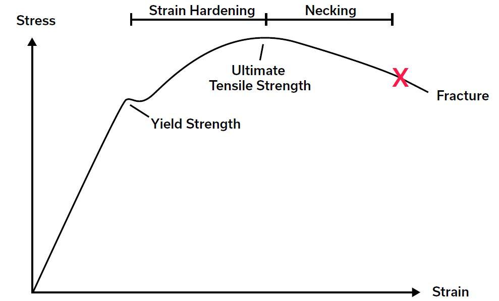
Figure 1 The stress-strain curve shows the yield strength, ultimate tensile strength, and fracture point.
Answer: Having my own shop at one time, performing the same kind of work that you are, I can tell you without a doubt that, yes, the formulas work on small-scale as well as large-scale materials. However, you did not mention your finished part tolerances. Having been there at one time, I’m guessing you work with values of ±0.001 in. and angles with half a degree of error. That is small for sure, but the error as a percentage of material thickness is about the same as it is for thicker material, at around 10% of the thickness. That makes it relatively easy to hold parts to specifications called for in the print.
Do you need to include the calculations for bend allowance and bend deduction? The answer is … sometimes. Yes, I realize that was a vague answer, so allow me to explain.
If you are forming with a punch-nose radius equal to or less than the material thickness, the calculated values are so small that, for the most part, they do not make much if any difference in the final part dimensions. That said, sharp bends still occur even at this scale—more on this shortly.
On the other hand, bend radii that are larger than the material thickness usually will require dealing with bend deductions and bend allowances because of the elongation that will occur.
To bend on such a small scale requires unique tools. First, find yourself some fine-ground, deep-edge-hardened (FG DEH) cutting rules, such as Sandvik Dieflex cutters. These are about 2 in. tall and razor-sharp on the cutting edge. Be careful. They can easily cut you to the bone just handling them. You might want to take a fine file and break the edge to make them safer.
When the punch radius is that sharp, even a bend with a material thickness of 0.010 in. can be bent sharp. You will need to watch for everything that a sharp bend implies. Use the same rule for larger bend radii and mount a piece of round stock with the correct radius to the punch.
For larger radius bends, make the punch just like we discussed. But here, I would form my larger bends in a urethane pad. Build a retainer box with an air channel under the urethane pad. The urethane pad needs to have a 50 to 60-durometer rating and be 10 times the volume of the material and punch radius. Urethane acts as a solid hydraulic and distributes the load equally in all directions, forcing the material to take on the punch profile (see Figure 2).
For bends that are close together on extremely small parts, you’ll need to get creative. Take four lengths of cutting rules, offset two of them a little, turn one pair over, and make an offset tool (see Figure 3).
Talk to your photo-etch house about half-etch lines centered on the bend line for the inside of the bend. This process establishes the bend line for bends in either direction.
One last tip: Centering your punch and die is one of the most essential parts of setting up a press brake. But the question is, how do you line up a razor-sharp punch that is 0.032 in. thick and center that in a die opening that is 0.04 in. wide? It is too small to see from a few inches away. A magnifying glass will not work because you cannot get close enough to use it, and you can’t stick your head between the bed and the ram, so how do you see it to center it?

Figure 2 Try forming your larger-radius bends over a urethane pad. Build a retainer box (left) that will leave you space to include an air channel under the urethane pad.
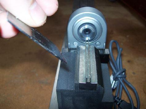
I’ve used two small webcams, made fixtures to hold them, mounted them to the bed rail, and plugged them into my laptop. It worked perfectly, with great views and perfect punch and die alignment (see Figure 4).
In conclusion, when you’re bending on such a small scale, be creative. It’s not as difficult as you think.
About the Author

About the Publication
subscribe now

The Fabricator is North America's leading magazine for the metal forming and fabricating industry. The magazine delivers the news, technical articles, and case histories that enable fabricators to do their jobs more efficiently. The Fabricator has served the industry since 1970.
start your free subscription- Stay connected from anywhere

Easily access valuable industry resources now with full access to the digital edition of The Fabricator.

Easily access valuable industry resources now with full access to the digital edition of The Welder.

Easily access valuable industry resources now with full access to the digital edition of The Tube and Pipe Journal.

Easily access valuable industry resources now with full access to the digital edition of The Fabricator en Español.
- Podcasting

In this episode of The Fabricator Podcast, Caleb Chamberlain, co-founder and CEO of OSH Cut, discusses his company’s...


