


Contributing Writer
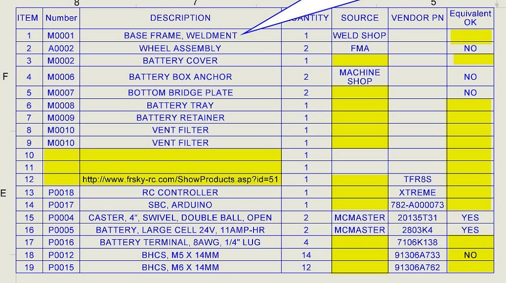
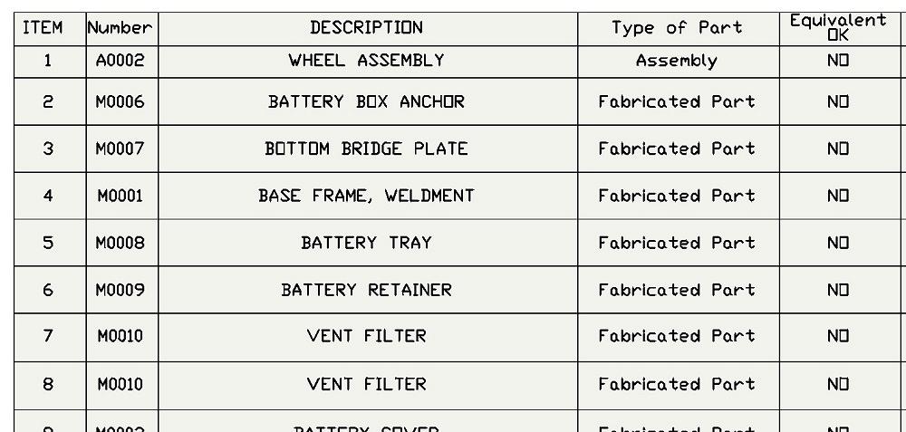
FIGURE 1A. The BOM table on our assembly drawing has several errors and omissions as indicated in yellow. Data entry is required for correction.
Time is money. Thus, the amount of labor put into a CAD model should be just enough and no more.
Some models are used only for visualization and will never be manufactured. In some cases, mainstream 3D CAD is used to export files to other CAM software for 3D machining or 3D printing. The models of interest for this discussion require the addition of product manufacturing information (PMI). PMI is challenging to convey with anything other than text—a supplier’s name, for example.
This ongoing series of articles is focusing on speedy tools for data entry of PMI, as well as how that stored PMI can be presented. The brand of 3D mainstream CAD being discussed allows PMI to be stored in parts, assemblies, and drawings. As for which bits of information to store where, that’s a matter of preference. That preference represents policy decisions for the CAD department.
Figure 1A shows a bill of materials (BOM) table. The CAD software makes dropping a BOM table like this onto a drawing an easy mouse gesture. Item numbers are assigned by the CAD software. The column titles and organization are determined by a BOM table template. At this stage in our scenario for documenting a product line, the design of that BOM table template may be subject to change.
If our data entry is complete, we expect the speedy result of a BOM table that populates itself. For example, the DESCRIPTION column has several entries that are complete. The yellow highlights in Figure 1A show where data entry is incomplete or in error.
In Figure 1B, the CAD workstation is set up to scan through the PMI for each component in the assembly. The plan is to select a component (either in the Feature Manager or Graphics Window), observe and correct the PMI, and then select the next component. This workflow can be very speedy. We may occasionally need to slow down to open a component in its own window for editing.
For this high-speed PMI editing session, we have the workstation divided into three sections: Feature Manager (left), Graphics Window (middle), and Custom Properties (right). The Custom Properties form is pinned to remain visible.
As with the design of the BOM template, our design of this Custom Properties form has been changing and is now being tested. Let’s follow the DESCRIPTION data from form to BOM table.
The Custom Properties form in Figure 1B is showing PMI found in the component that is selected in the Feature Manager. In the Feature Manager, the first component in the assembly “M0001” has been selected—as indicated with the blue highlight in the Feature Manager. The PMI for “M0001” is being displayed in the Custom Properties form.
The description field on the form is emphasized in Figure 1B. The value entered here, BASE FRAME, WELDMENT, is what is being displayed by the BOM table back in Figure 1A.
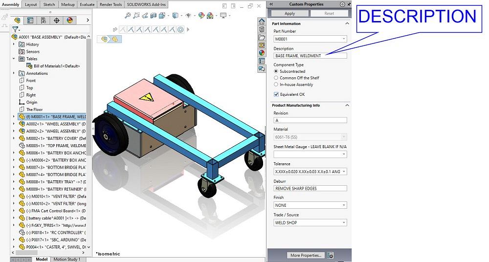
FIGURE 1B. The workflow is proposed: Select a component so that the form displays its PMI, use the drop-downs to speed the typing, save and select the next component. This workflow can proceed briskly. The description entered here appears in the BOM table, as seen in Figure 1A. Our form is testing successfully.
Here’s a CAD Tip: The description might be edited using the Custom Properties form, as shown in Figure 1B. It also might be edited by double-clicking on the appropriate cell in the BOM table.
Figure 2A shows a different BOM table design for the same assembly. We will review each of the column headings in a moment. This BOM table displays all of the PMI collected in our system by CAD department policy.
Note that with a workstation setup like this, a CAD jockey can easily access the Custom Properties form with its data entry helpers, and it’s equally easy to double-click on any cell in the BOM for editing.
A review of the PMI in this BOM table follows. In Figure 2B, the first few columns from the giant BOM table presented in Figure 2A are shown for legibility.
We have used mouse drag-and-drop gestures to sort the rows to put assemblies first, followed by custom-made items, followed by off-the-shelf items.
Here’s another CAD Tip: The sequence of columns also can be changed with drag-and-drop, and columns might be added or deleted from the BOM table. To create a template from the BOM table, the SAVE tool does the trick.
The ITEM numbers are assigned by the CAD software when the BOM table is generated.
According to our CAD policy, the number is assigned by retrieving it from a log. If a component has configurations, it might have unique numbers assigned to each configuration. This capability is used in our battery cable model; one configuration shows the black insulation, another shows the red, each with the corresponding vendor part number.
The Type of Part is PMI designed into our data entry system, mostly to control the Custom Properties form. This is a radio-button controlled selection on our Custom Properties form. Type of Part causes a different set of data entry fields to be presented on the Custom Properties form, depending on the setting. This data might be useful to the purchasing department when organizing drawings for use by the supply chain.
Equivalent OK allows the purchasing department to exercise some discretion. Off-the-shelf items might be available from several suppliers. A nut is a nut, for example.
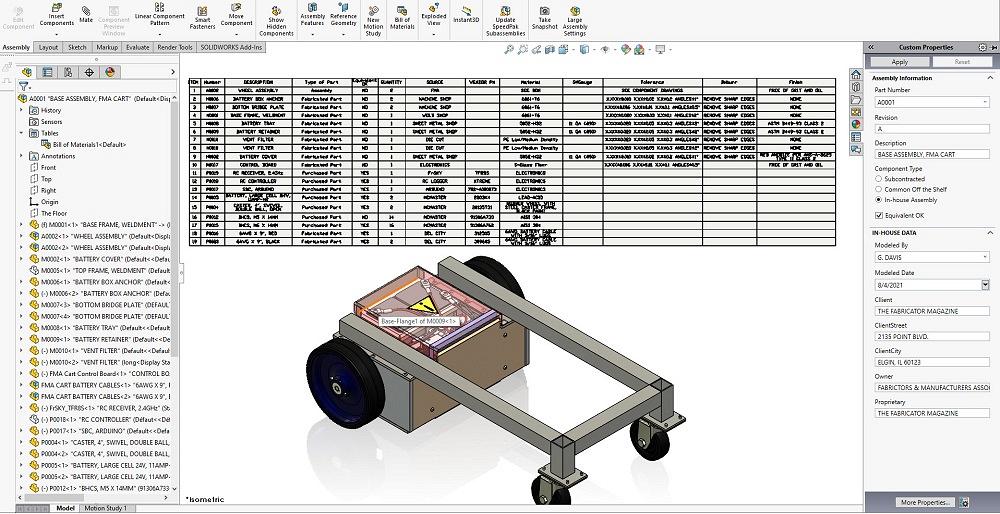
FIGURE 2A. A BOM table with columns showing all of the PMI entries available on the Custom Properties form is inserted into an assembly. BOM tables aren’t just for drawings. Double-click to edit a cell in the table or select a field in the form, whatever is fastest.
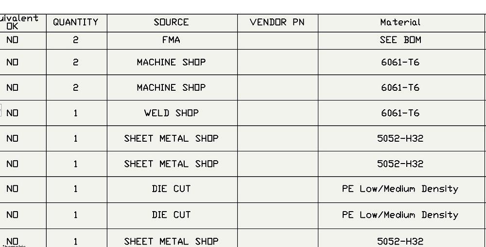
Figure 2C reviews some additional columns. The quantity for each line item is filled in by the CAD software. We note that our BOM table template will change the default heading from QTY to QUANTITY as part of our CAD policy.
We also note that the headings are in various states of upper and lower case. This matches the names of the PMI entries as the form was designed. That mix of case is contrary to our policy and is something that is easy to correct using a BOM table template.
SOURCE tries to indicate the trade involved—sheet metal, machine shop, die cut, in-house labor. When the source is a vendor, the vendor’s name appears here.
If the item is purchased using a part number specific to a vendor, the VENDOR PN will show it.
The Material column was discussed in detail in the previous episode. Suffice it to say, when material is assigned to a component, this data element is filled in.
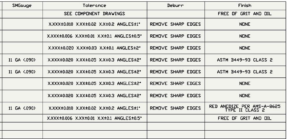
To conclude this review of our PMI system, Figure 2D shows our final four columns. SMGauge (sheet metal gauge) is used to complete the tile block on drawings. Our Custom Properties form includes a drop-down list for easy selection of gauges in aluminum, steel, and stainless sheet.
As with the sheet metal gauge, Tolerance, Deburr, and Finish also will appear on 2D drawings. Using this BOM table inserted into the assembly, a CAD jockey can easily review the consistency of the tolerances used.
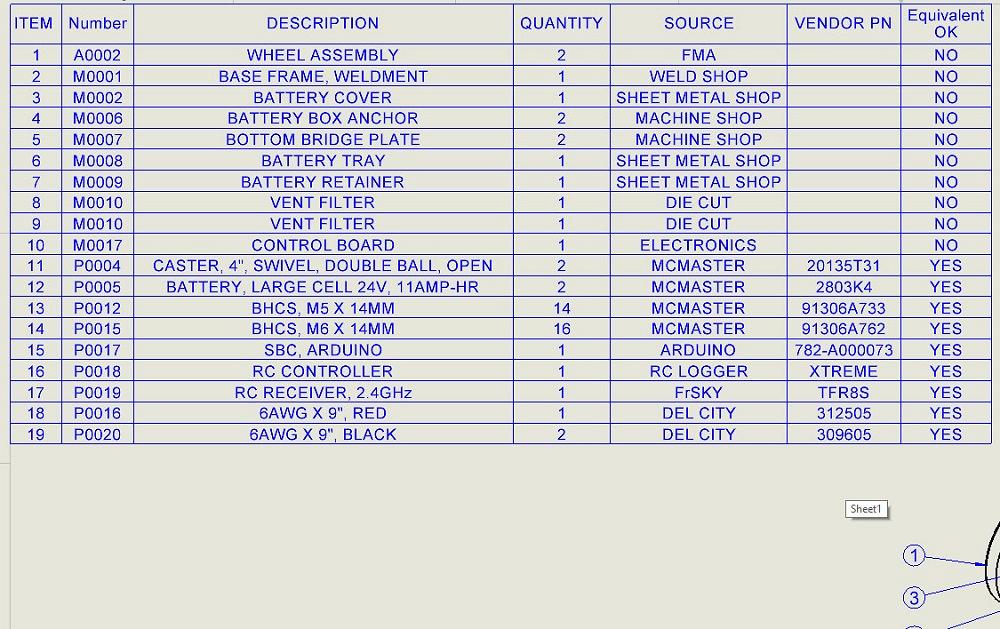
Once this data entry form is used to complete the PMI, the BOM table on the assembly drawing is ready (see Figure 3). All of the purchased items indicate that equivalent items are permitted, vendor names and part numbers are shown, and trades are indicated for custom components.


The Fabricator is North America's leading magazine for the metal forming and fabricating industry. The magazine delivers the news, technical articles, and case histories that enable fabricators to do their jobs more efficiently. The Fabricator has served the industry since 1970.
start your free subscription
Easily access valuable industry resources now with full access to the digital edition of The Fabricator.

Easily access valuable industry resources now with full access to the digital edition of The Welder.

Easily access valuable industry resources now with full access to the digital edition of The Tube and Pipe Journal.

Easily access valuable industry resources now with full access to the digital edition of The Fabricator en Español.
In this episode of The Fabricator Podcast, Caleb Chamberlain, co-founder and CEO of OSH Cut, discusses his company’s...


