


Contributing Writer
klyaksun / iStock / Getty Images Plus
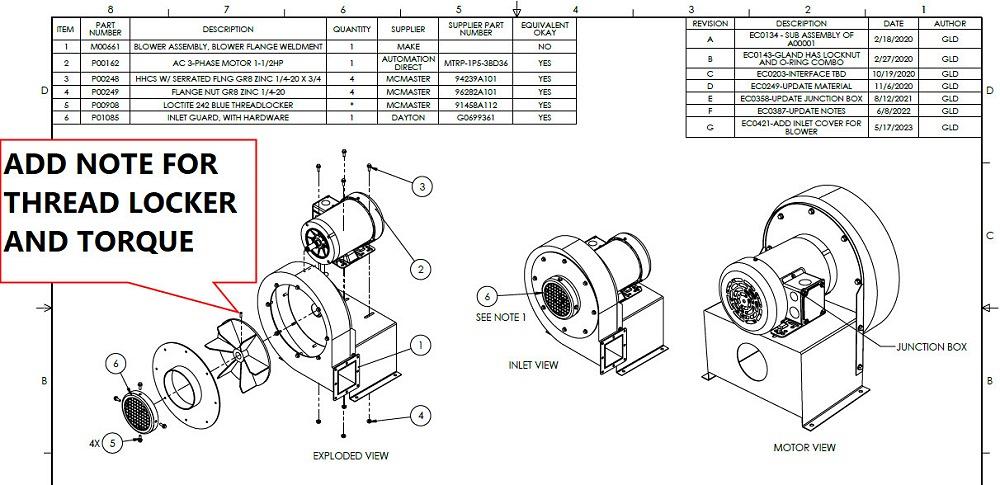
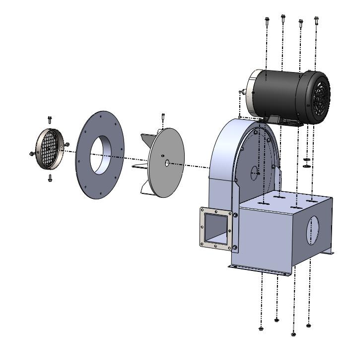
A problem has been reported and redlined on an assembly drawing as shown in Figure 1A. The problem is that the exploded view of the assembly is incorrect. The illustration does not show that a cover must be removed to gain access to the set screw in the fan wheel for connection to the motor’s shaft.
A revised drawing is presented in Figure 1B. The cover and fan blade, with its set screw, have a more informative orientation. The reviewers approve that revision.
“But, while you’re at it,” they say. Figure 1C shows the suggestion to add thread locker and torque specification for the set screw. Such is the nature of the role of sustaining engineering for a CAD jockey: All revisions are subject to revision.
The differences between Figures 1A and 1B are relatively minor:
These revisions should not have taken much effort. However, unlike the ideal, the CAD model is a combination of multibody parts and assemblies. Basically, a legacy of tangles because of the accidental evolution of CAD talent and of the design intent over a period of years.
The first modeling goal centered on the need to hook up a standard blower to a custom duct. At the time, a 3D CAD model for the off-the-shelf blower was not available, so an approximation was made, mostly using a tape measure and reference photos.
What mattered initially was the size and shape of the custom flange that needed to be welded to the blower’s nozzle. The internal components of the blower itself were not modeled very accurately. Attention was paid to the nozzle and its location relative to the mounting feet.
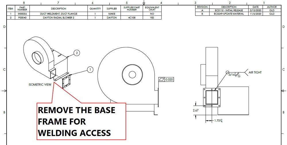
The bill of materials (BOM) table in Figure 1A lists Item 1 as part number M00661—the previously mentioned blower-to-flange weldment. The drawing for that weld is shown in Figure 2A. Its BOM table lists the components to be welded, a custom flange (M00056) and an off-the-shelf blower (P00040).
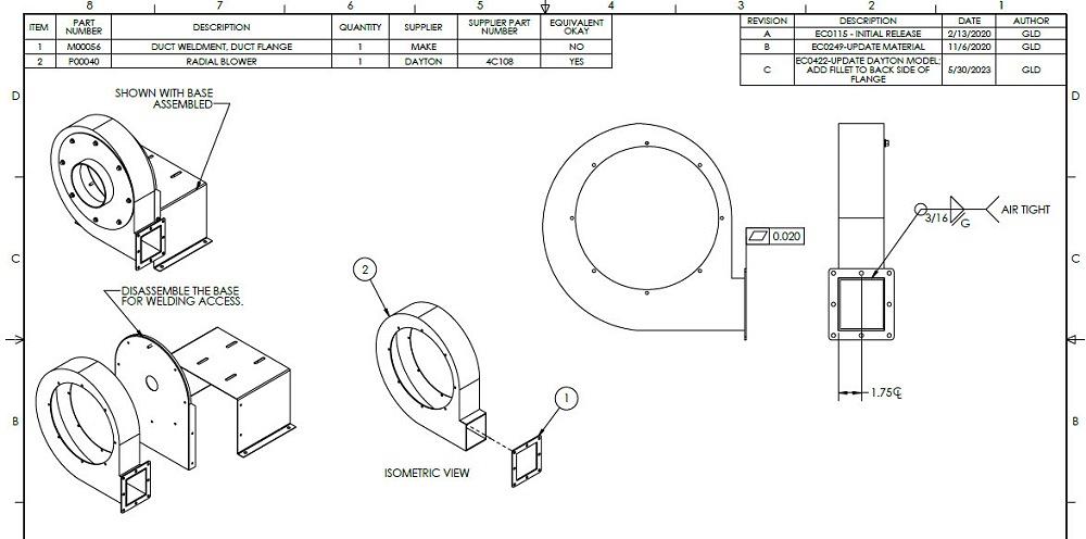
The note in Figure 2A is another offered by the critics. The welding would be easier if the base is dismounted from the blower housing first. Figure 2B has a more realistic representation of how the blower is bolted together and is ready for tolerance review and final release.
Comparing Figures 2A and 2B shows that the original model for the blower did not show the separate pieces of sheet metal, nor did it show the bolts.
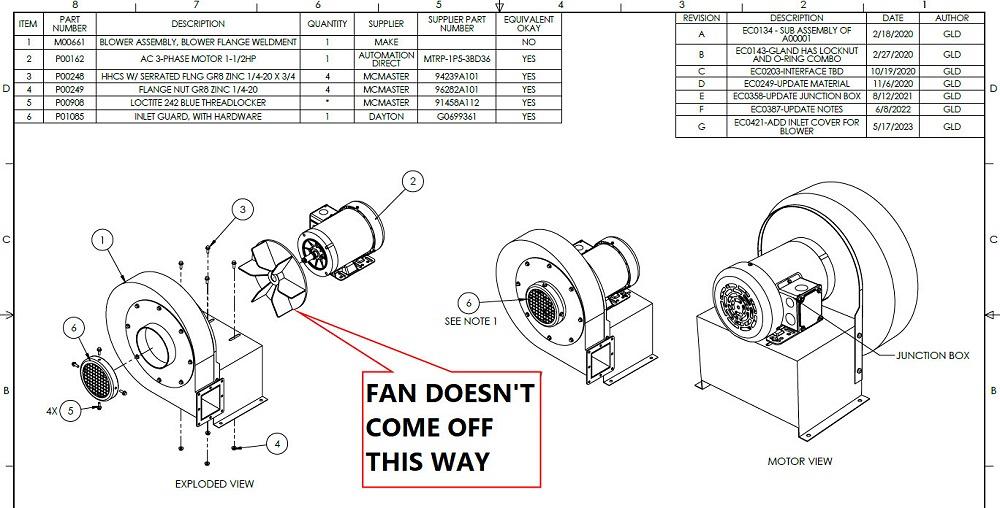
FIGURE 1A. The error on this drawing requires correction. The Exploded View is incorrect.
With the hindsight gained from extensive editing of the 3D model to make a relatively small change to the 2D drawing, what would be the right way to model this project?
The way it was done, right or wrong, was what it took to get it done. Shortage of time and excess of prototypes were realities that set priorities. Focus had to be on the mission-critical items and their shortest path. The way it was done was to postpone work that seemed to be embellishment and frills.
Sidebar: To add nuance to the differences between the model that evolved and what a hindsight-driven model would be, here is a brief review of technique and terminology. Within the brand of mainstream 3D CAD being used in support of this article, the 2D drawing shows a projected view of a 3D model. The 3D model positions its components as needed for purposes of the 2D illustration.
The components in the 3D model may be positioned with any combination of the Explode tool, Body Moves, or with Mates. Moves (and Mates) can interfere and conflict with each other, thus Configurations are sometimes used to control when and which set of special-purpose mates and moves are in effect.
Configurations also can be used to control which set of components will be mated. Display States can be selected to determine which set of components are visible, selected either by the configuration or by the drawing’s view. Brief exposure, indeed.
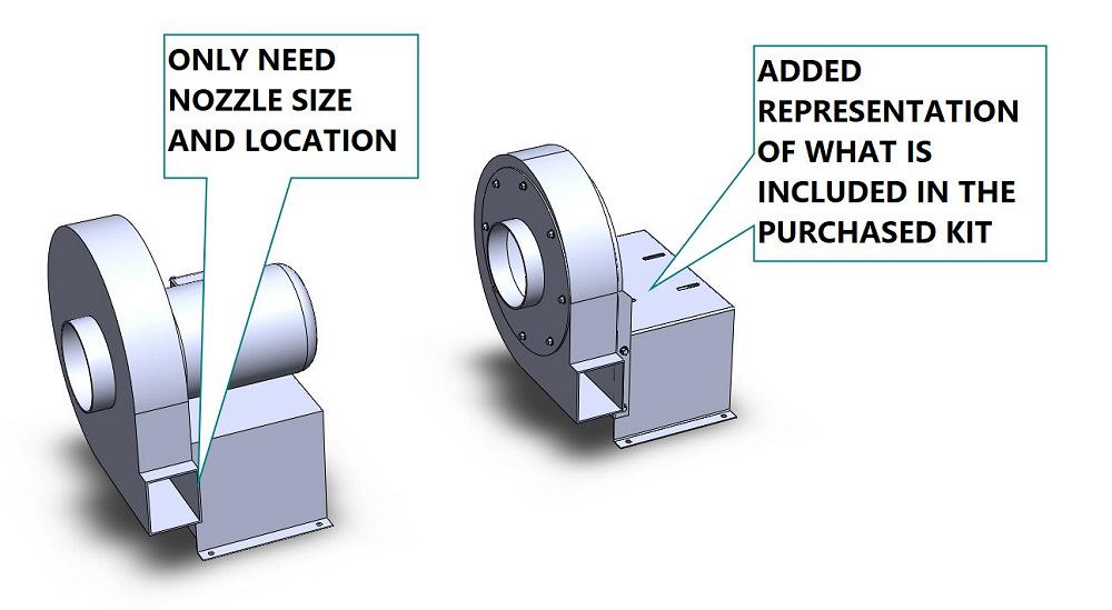
Figure 3A provides a comparison between the starting point (to the left) and the current version (to the right). The starting model focused on the nozzle. That feature was used to model other components in the next-level assembly. The current model maintains that and represents all the pieces and parts that are included as part of the blower.
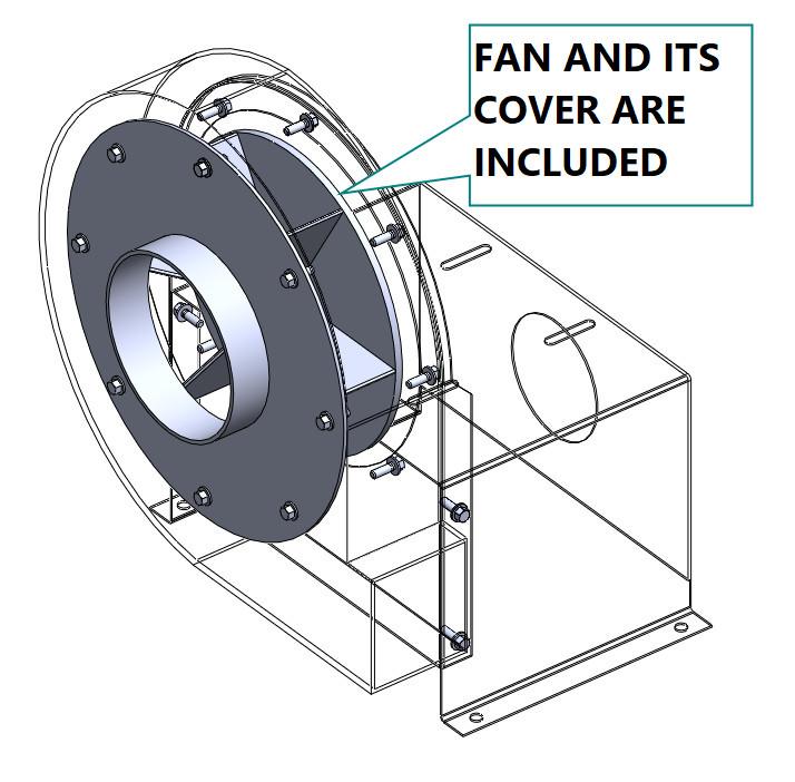
The blower comes with a sheet metal base, a base upright, a housing, a wheel fan, and a fan cover. The latter two items are visible in Figure 3B. The bolts and nuts (and a set screw for the wheel fan) are included. The motor is not included.
These blower components are modeled as bodies in a multibody part. They are reasonably accurate, but not suitable for fabrication. The technique of multibody modeling is largely driven by legacy. The tools for exploding a multibody are similar to, but not the same as, exploding an assembly of components. That is perhaps the greatest difference between how it started and what it could have been.
The various bodies, parts, and subassemblies shown in Figure 3C are the result of satisfying demands in BOM tables. The BOM tables do not require Exploded Views, however it helps to see how the parts are to be assembled.
The distinction between custom-made, modified off-the-shelf, and fully off-the-shelf items affects the level of detail and effort put into the 3D model. Basically, don’t model details that don’t need controlling or to be controlled.
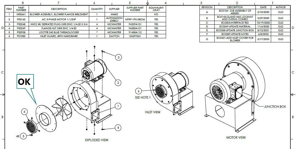
FIGURE 1B. The corrected drawing shows the relative positions of the inlet cover, the fan cover, the fan, and housing in a more informative layout.
How the components are obtained (Where does the set screw come from?) also affects the method of modeling. Perhaps a multibody part is the best way to control the CAD and to represent items that arrive under the same part number.
With hindsight, the multibody technique made the edits to the top-level Exploded Views more difficult. That is to say, more Configurations and Display States were used than would be required if this was simply an assembly of parts.
Having just typed that, I wonder why I didn’t just export the bodies as step files and reassemble them to make the ideal Exploded Views for creating BOMs and illustrations.


The Fabricator is North America's leading magazine for the metal forming and fabricating industry. The magazine delivers the news, technical articles, and case histories that enable fabricators to do their jobs more efficiently. The Fabricator has served the industry since 1970.
start your free subscription
Easily access valuable industry resources now with full access to the digital edition of The Fabricator.

Easily access valuable industry resources now with full access to the digital edition of The Welder.

Easily access valuable industry resources now with full access to the digital edition of The Tube and Pipe Journal.

Easily access valuable industry resources now with full access to the digital edition of The Fabricator en Español.
In this episode of The Fabricator Podcast, Caleb Chamberlain, co-founder and CEO of OSH Cut, discusses his company’s...


