


Contributing Writer
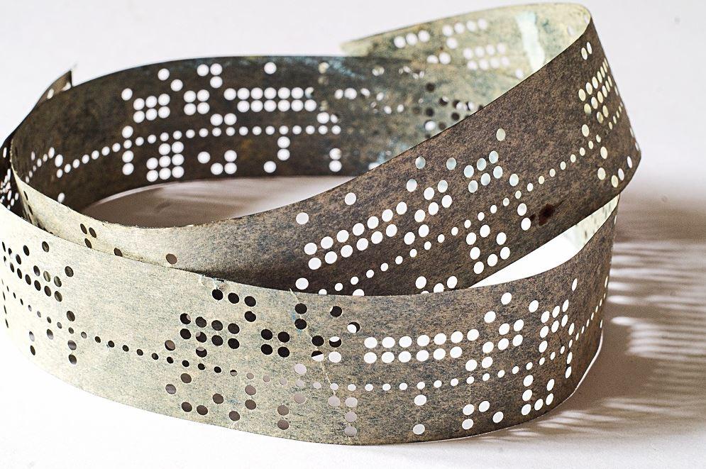
CNC controllers once used punched paper tape for program storage and recall. The length of the tape mattered. Shorter was better. NataGolubnycha/iStock/Getty Images Plus
In the late 1970s, I was paid to play with G-code canned cycles, fixed programming instructions that help CNC equipment perform repetitive operations. The length of the paper tape was one measure of the program quality.
In addition to standard canned pecking cycles, CNCs featured (and still do feature) brand-specific G-codes for bolt hole circles, lines of holes, and curved patterns of all kinds. In the days when programs were stored and recalled on punched paper tape, a fabricator’s use of G-code macros and canned cycles was important.
To use the G-code effectively, CNC programmers recognized patterns and coded for them to take advantage of the controller’s capability. Honestly, I’m no longer that good at CAM. Software has improved over the past several decades and relegated my paper tape skills to the buggy whip pile.
From this kibitzer’s perspective, when CAM apps automatically generate the G-code, simple X-, Y-, and Z-moves can be the result. The programmer doesn’t have to worry about a specific brand of controller or postprocessor, recognizing patterns, or the program length. (Old timers pause to snicker.)
In the realm of mainstream 3D CAD, an extrude is a small part of the overall modeling process, comparable to a G-01 XYZ move in a CAM. In CAD, with enough bosses and cuts, the model can probably be made. With enough X, Y, and Z moves and tool changes, the part can probably be carved.
To strain the analogy between CAM and CAD tools further, this CAD jockey would like to discuss CAD operations that, like canned cycles in G-code, help with efficiency and lessen the modeling effort. As an example, please consider the Cut Sweep with Solid Profile.
Figure 1 shows three versions of a part in cross section. The curved slot is the difference between these versions being either extruded, filleted, or swept. On the left in Figure 1, a simple Cut-Extrude is used as a starting point, then Move-Face is used to rotate floor. This is elemental CAD modeling, however. The resulting 3D model would be difficult to machine with a rotating cutter.
To address that design for manufacturability problem, the channel edges could be filleted. The result sort of looks like something a ball mill could carve. However, each fillet in the pair is following a separate path—not quite what a single pass with a ball mill would leave behind.
To address that problem, the model on the far right in Figure 1 was made using a sweep of a solid body (representing the rotating cutter) along a single path. This removes material just as an end mill would.
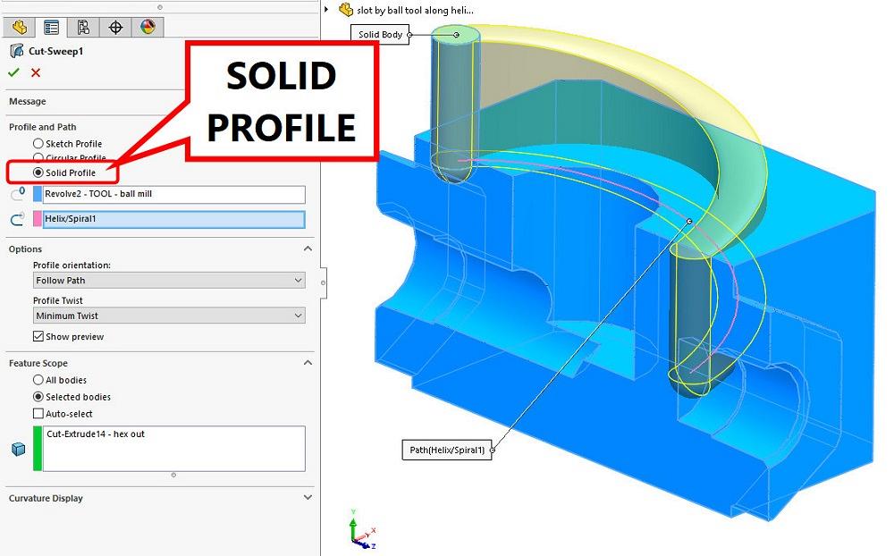
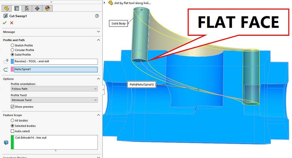
Figure 2A shows settings in the Feature Manager for the Cut-Sweep with solid profile. Note the radio-button setting to select Solid Profile. For this option to work, the tool body must exist first. So, we backtrack to model the tool body. In real life, the CAD jockey would know the sequence of modeling required.
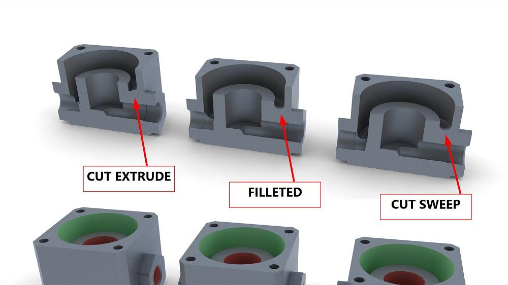
FIGURE 1. A comparison of three modeling techniques for a spiral groove is shown. On the left, a Cut Extrude/Rotated Face; in the middle, a model with fillets added; and on the right, an example that was modeled with a swept tool body, keeping design for manufacturability in mind.
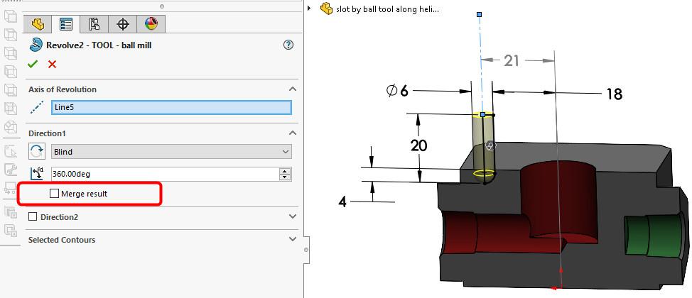
Figure 2B shows the setup for creating the tool body from a Revolved Sketch. Note the setting (unchecked) for Merge result creates the required separate body for the cutting tool. The tool body shown in Figure 2B has a radiused end to resemble a ball mill. One of the limitations on the tool body is that it is a trenching tool; it cannot have undercuts (a thin stem) like some ball mills have. Another consideration to keep in mind is the starting point of the path that the tool will follow. The start point must be coincident to the plane used to create the rotated tool body.
Ball mills, radiused cutters, and chamfered cutters are modeled in the same manner. Figure 2C shows how a flat-faced end mill would cut a spiral groove. The floor of the groove would not be flat due to the tangent pass of the spinning blades as the cutter moves down the spiral.


The Fabricator is North America's leading magazine for the metal forming and fabricating industry. The magazine delivers the news, technical articles, and case histories that enable fabricators to do their jobs more efficiently. The Fabricator has served the industry since 1970.
start your free subscription
Easily access valuable industry resources now with full access to the digital edition of The Fabricator.

Easily access valuable industry resources now with full access to the digital edition of The Welder.

Easily access valuable industry resources now with full access to the digital edition of The Tube and Pipe Journal.

Easily access valuable industry resources now with full access to the digital edition of The Fabricator en Español.
In this episode of The Fabricator Podcast, Caleb Chamberlain, co-founder and CEO of OSH Cut, discusses his company’s...


