


Contributing Writer
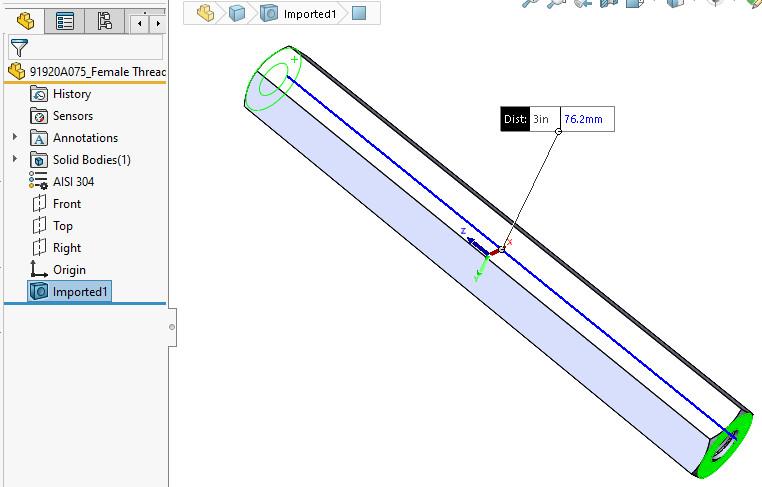
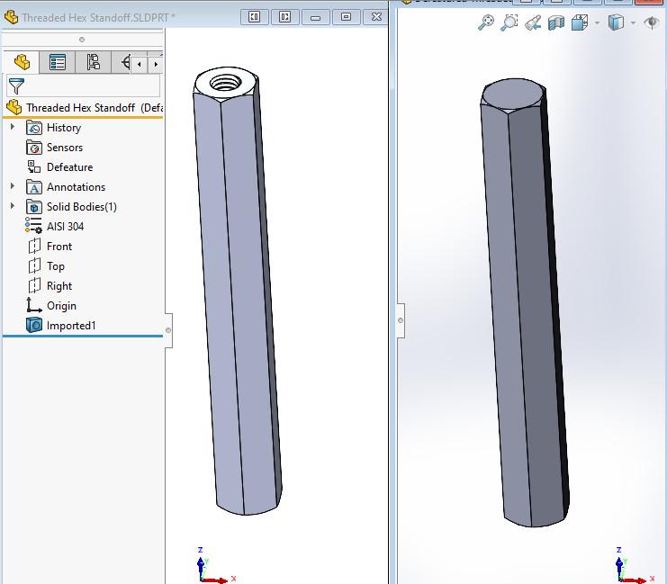
FIGURE 1. This model of a hex standoff started out as a downloaded part. However, that part was of a Future Version, so it was exported as a Parasolid, then imported and saved as a .sldprt.
Imported CAD models often are preferable to detailed native CAD creations, particularly for commodity items that will be purchased rather than manufactured. Such “poser” models typically are used in three ways: to populate a bill of materials table, as actors in a virtual prototype, and as a starting point for a new design.
Figure 1 shows an example of such a downloaded import. Here, a 3-in. hex standoff is the star of the show. We obtained this model by visiting a hardware store website and retrieving a 3D file (.sldprt). Future Version incompatibility forced the file to be exported as a Parasolid (.x_t) file. That Parasolid was imported and exported as a .sldprt in Old Version to create a compatible CAD model.
We might use this hex standoff several times in the FMA cart. The imported model has no design history—it is the epitome of minimalist. For the cart application, that is ideal. Having an efficient model (speedy rebuild and reliable size characteristics) is a blessing for this actor.
As a side note, we are assigning mass properties to all the components of the cart project to support evaluation of its design and prediction of its behavior.
For the time being, we apply stainless steel as the material and appearance for the hex standoff. If it turns out to be good for the design, additional time will be taken to add the product manufacturing information (PMI) such as supplier and supplier’s part number.
For this exploratory model, we need to avoid extraneous detail and superfluous effort. We assigned material to the component simply because the next step is to see how it looks, and perhaps to discover how the material changes center of mass when used in the assembled cart.
While being speedy—that is, skipping past details being typed into the right place—it’s lucky that the part number is the filename and the part number implies the description and source, so no additional effort is needed for data entry of PMI at this time.
An evaluation of the component shows that it is the wrong length. At this “fork in the workflow road,” we can either revisit the hardware store’s website and download another hex standoff model or simply modify the model on hand. The download/PMI process takes a few minutes. How long would a modify/update PMI workflow take?
To create a model that is the same except for the length, we’ll consider two workflows: Move and Mirror. We’ll start with the latter, then examine the more moving workflow later.
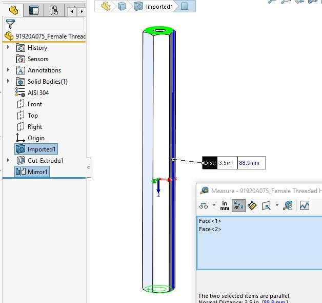
The Mirror workflow is to cut the model to half the desired length, then mirror it to achieve glory. Figure 2A shows a sketch to cut the model. This may be a controversial sketch. It is a single line segment—a very simple and quick jot.
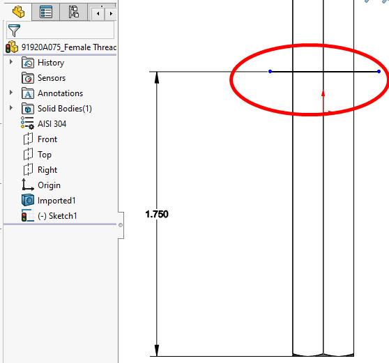
FIGURE 2A. The circled line segment will be used to cut the model. This simple sketch is speedy and is not fully constrained. That lack of constraint could be problematic, so use this technique with caution.
The ends of the line segment are not constrained as a consideration of time. Gasp! The controversy is that if the constraint is not essential to the design, we shouldn’t add it.
Side note: Murphy’s law applies. If a sketch is not fully constrained, it will become a problem sometime in the future when it drifts into an uncontrolled and nonfunctional condition. Saving time in exploration early in the process will result in spending time later establishing dominance over the model.
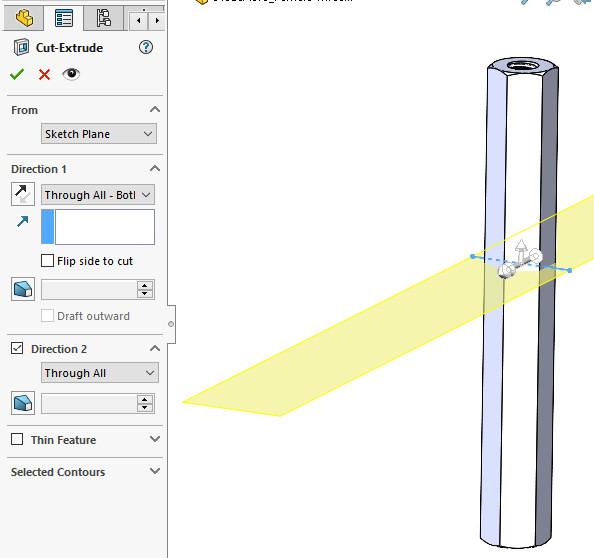
The 1.750-in. dimension in Figure 2A was derived from half of 3.500 in. Figure 2B shows the settings for the next step, a Cut-Extrude. It is cutting Through All in Both Directions, with the direction of cut designed to leave the good bit behind.
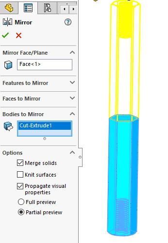
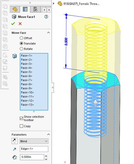
Figure 2C shows the Mirror feature—the freshly cut half body is mirrored and merged into a single body. In Figure 2D, the result is measured to confirm the 3.500-in. length. That’s the end of the cut-and-paste demo, which takes maybe a couple of minutes.As promised, we turn to an alternative workflow to achieve the same result (see Figure 3). The Move Face feature is added to the imported model to relocate all of the faces on one end of the standoff (the threads and chamfers of the standoff). Were it not for all of these faces (and the clicking to select them), the Mirror workflow would not have been considered.
With the faces selected, we use one of the edges of the hex standoff to set the direction of translation. That’s the end of the stretch demo. This workflow is perhaps easier to edit than the mirrored version. Referring to the menu bar, Insert>Face>Move finds speedy application in many situations.
The discussion now shifts slightly from modifying an import to the amount of detail to include or exclude in a “poser” model.
A detail such as helical threads may be irrelevant to getting the final design released. In fact, the threads may slow down the effort of kinematic mating of components in the design. Spirals will certainly require CPUs to process the curves and features of the threads.
There’s a tool to relieve that burden: the Defeature feature. Figure 4 shows a side-by-side comparison of the original imported model (left) and a defeatured model. The defeatured model will rebuild faster than its parent. Its origin, surfaces, and planes remain very suitable for mating in an assembly. Yes, it is a simplification of the real part. Yes, it is quick.
As a side note, the Defeature tool comes in handy when presenting 3D models for public consumption when internal details do not need to be revealed.


The Fabricator is North America's leading magazine for the metal forming and fabricating industry. The magazine delivers the news, technical articles, and case histories that enable fabricators to do their jobs more efficiently. The Fabricator has served the industry since 1970.
start your free subscription
Easily access valuable industry resources now with full access to the digital edition of The Fabricator.

Easily access valuable industry resources now with full access to the digital edition of The Welder.

Easily access valuable industry resources now with full access to the digital edition of The Tube and Pipe Journal.

Easily access valuable industry resources now with full access to the digital edition of The Fabricator en Español.
In this episode of The Fabricator Podcast, Caleb Chamberlain, co-founder and CEO of OSH Cut, discusses his company’s...


