


Contributing Writer
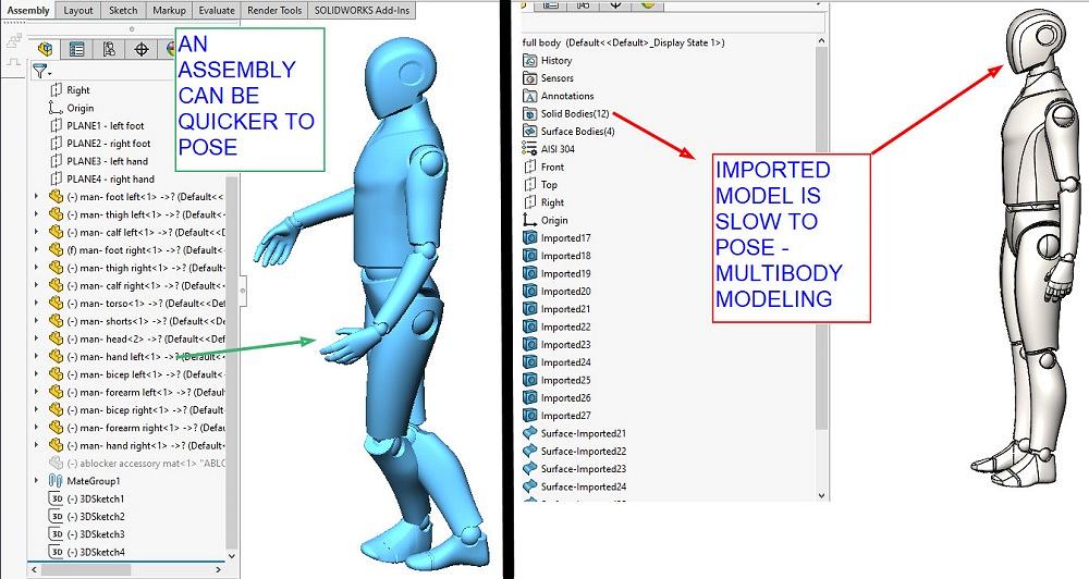
FIGURE 1. A posable assembly (left) was created from a downloaded multibody statue (right). Mates were added in the assembly to allow the head to pivot on the torso, and so forth.
My most successful projects as a contract designer have derived from three skills. The production of thorough documentation has proven to be a competitive advantage in getting products to market. Complete detail regarding product manufacturing information (PMI) is paramount. Skill with PMI will be an ongoing theme in these episodes.
The completed designs and 3D models reflect best practices in manufacturing, relying heavily on input from the fabrication crew to refine the design for tooling, fixturing, and processing sequence. To be clear, I’m good at using CAD to capture suggestions. I am merely functioning as a stenographer listening to other experts and visionaries on the project. Design for manufacturing (DFM) is what it is all about.
The third leg of success has been in presenting the design for review, often on a moment’s notice. In many situations, posable models serve as useful actors to present the operation of the product under development. The audiences for such presentations are many—collaborators, assemblers, investors, and end users.
Posable models come in all forms, maybe a chair, a hammer, or who knows what. A mannequin is an extreme example, but it has a knack for being a good story teller. Figure 1 features an example “bot” model posted on GrabCAD by the very talented Lano Kuyama.
The download of Kuyama’s model results in a multibody part file, a “statue” as shown to the right in Figure 1. We note that the solid bodies in this multibody model have no freedom of movement. Mouse-drag has no effect on them, although there are other ways to position the statue.
A posable (kinematic) assembly, made from pieces of Kuyama’s statue, is shown to the left in Figure 1. Unless mates are used to constrain their degrees of freedom, the parts in an assembly move easily, oddly, or independently with mouse-drag.
If a picture is worth a thousand words, creating an animation tests one’s patience a thousand times. The balance between result and effort tilts toward short and simple animations. If the animation is lengthy, work on it in short segments, perhaps joining several short videos from several Motion Studies using postproduction software. The results of the Motion Study can be exported in the form of a video, an MP4 file type, for example.
Here's a sidebar discussion: Using terms from a brand of CAD, this CAD jockey refers to a “Motion Study” as one of several tools for making an animation. The May 2016 episode of this column covered the Mate Controller, another useful tool for posing and presenting designs.
The Motion Study has a Basic Motion mode that can be used to simulate things like gravity and springs. For this mannequin’s motion, we will be using the Motion Study in Animation mode to follow path mates.
Regardless of the brand of CAD being used, success is attracted by planning. A story—explaining the use or function of the product being presented—leads to a story board. The story board example shown in Figure 2 is useful for planning the placement of key points in the Motion Study, seen in Figure 3.
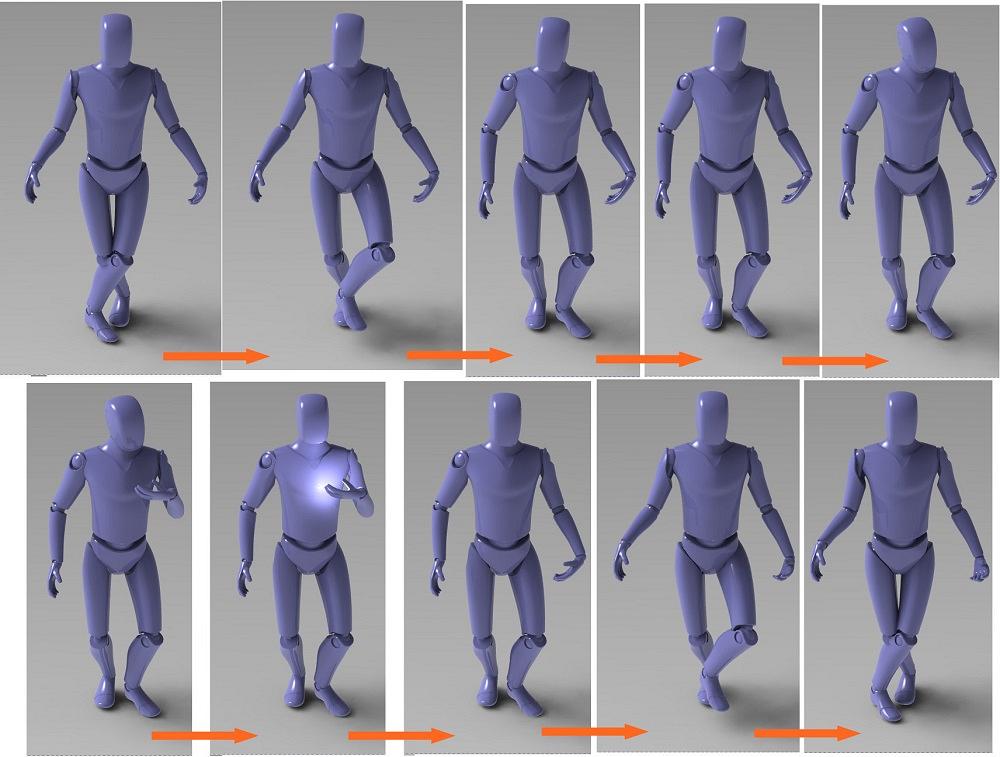
FIGURE 2. Each scene in a story board becomes a set of key points along a timeline in a Motion Study. Here we watch my customer being interrupted to receive my invoice for this animation.
Each scene in the story board is a snapshot along a timeline of the model posed in different positions. The CAD software will do its best to fill in the transitions between the scenes. If the transitions create impossible motion, try simplifying the constraints. And back and forth revising the transitions and paths until it works.
Here are some tips for mating while working with Motion Studies:
The parts shown in the assembly in Figure 2 (the arms, the legs, and other parts) have a chain of mates added by the author to constrain their degrees of freedom. For instance, the hip bone is connected to the thigh bone, which is connected to the foot, and so on.
Story Version 1.0 was to set up an animation of the “bot” pushing the FMA cart for a step or two. With the feet fixed in position near the floor, the head was given a yank with the mouse toward the ceiling.
A happy accident created a starting pose. The goal of the story quickly evolved from a cart demo into a generic gesture. Story Version 2.0 became what happens when I send my client an invoice for producing this animation. Here’s the result:
As mentioned, the CAD software calculates the transitions between key points. In Figure 3, along the bottom, we see four path mates and their key points (little blue diamonds) dotting the timeline in the Motion Study.
Where two diamonds are connected with a blue bar, something is changing. Sometimes key points are repeated (copied) to prevent motion for a period of time.
Here’s a CAD tip: Before launching the Motion Study, organize (mouse drag) the mates in the Feature Manager to group them at the bottom of the list of mates. They will then be easier to find in the Motion Study. That’s why they all appear nicely in a group at the bottom of Figure 3.
The 3D sketches used for the path mates vary in complexity. The left foot lifts and swings dramatically. The shin is locked (CAD term) to the foot, and the thigh is constrained to the shin and pelvis with concentric mates. The sketch that moves the torso is a simple short line.
Here’s one more CAD tip: The lock mate can constrain degrees of freedom nicely in a Motion Study. My favorite trick is to use key points to suppress and then immediately unsuppress the lock mate in the Motion Study. Then a return to time zero (where the lock mate is suppressed) allows rebuild (ctrl-Q) to restore joy to the chain of mates as they complain about being forced around by the Motion Study.
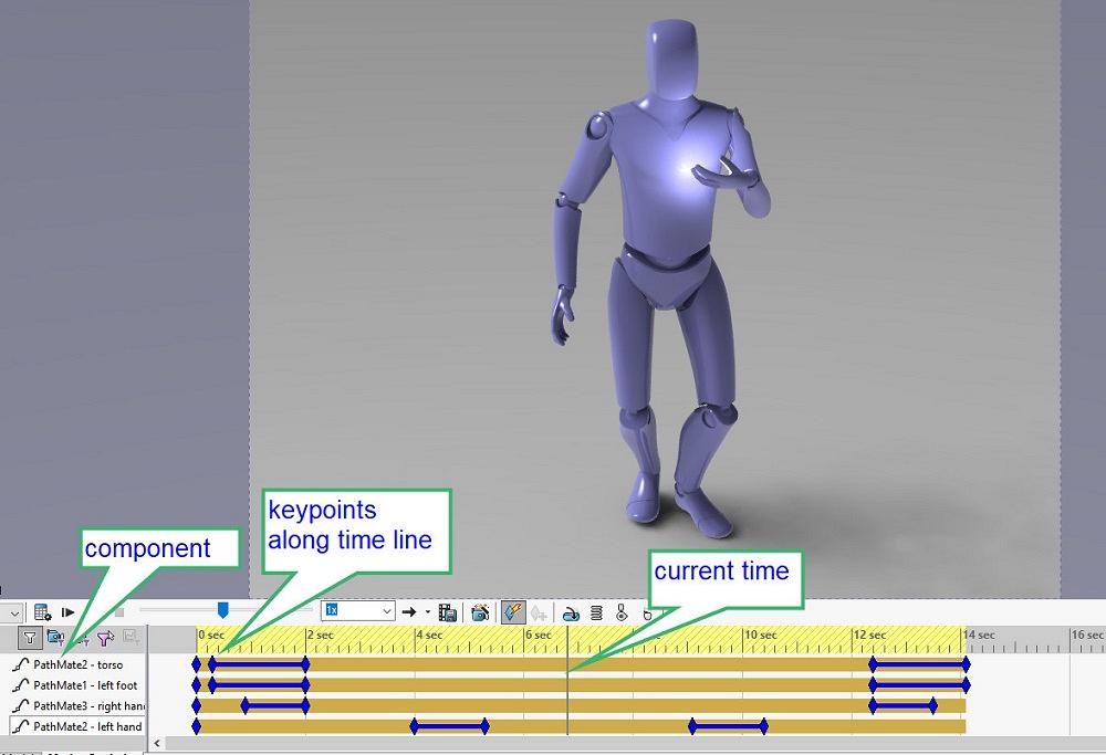
FIGURE 3. CAD tip: To reverse motion, copy, paste, and reverse the path of a pair of key points. Key points along a timeline in a Motion Study are shown (little blue diamonds). Each row corresponds to a component’s mate, in this case a path mate. Each key point sets a distance along that path mate. The location of the key points along the timeline sets where the motion along the path will occur.
Not shown in Figure 3 are the key points that control the locking of the foot to the shin. Also present, but off-screen, are the key points that control the on/off of lighting and the nodding of the head. Head motion was accomplished by mouse-positioning of the head and relies entirely on a concentric mate with the torso.
I have to make another guilty confession, this time about planning after the job is complete. The completed Motion Study was used to create the story board presented in Figure 2. Rendering in a spot along the timeline with Integrated Preview turned on takes a moment to complete but results in a pretty picture.
To assemble the image that is Figure 2, we saved a screenshot. Then the time-bar was moved to the next significant point on the timeline. (Pause for rendering to complete before another screenshot.) Then those screenshots were used as if they were premediated hand-scribbled cartoons.
With a setting of 30 frames per second, the Motion Study was exported as an MP4 file type using the Photo View rendering.


The Fabricator is North America's leading magazine for the metal forming and fabricating industry. The magazine delivers the news, technical articles, and case histories that enable fabricators to do their jobs more efficiently. The Fabricator has served the industry since 1970.
start your free subscription
Easily access valuable industry resources now with full access to the digital edition of The Fabricator.

Easily access valuable industry resources now with full access to the digital edition of The Welder.

Easily access valuable industry resources now with full access to the digital edition of The Tube and Pipe Journal.

Easily access valuable industry resources now with full access to the digital edition of The Fabricator en Español.
In this episode of The Fabricator Podcast, Caleb Chamberlain, co-founder and CEO of OSH Cut, discusses his company’s...


