


Contributing Writer
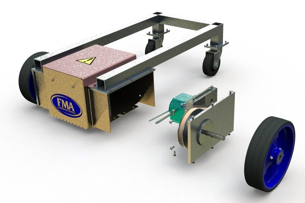
FIGURE 1. This cart is the product we’re using to discuss the setup of data entry forms so that we can discuss the setup of drawing templates. Then we can start making drawings.
The FMA cart shown in Figure 1 is a project that has served as a framework for discussion in several recent episodes of this column. The focus of the CAD effort is currently on the documentation for fabrication. We anticipate a cycle of refinement and revision to the initial 3D design once these preliminary drawings are complete. Nonetheless, the mindset is that we are beginning work on final drawings.
Disclaimer: This demo is realistic, not real. We’re trying to avoid collision with commercial products and trademarks while at the same time showing actual forms, templates, and CAD techniques. The cart is merely representative of a product.
The FMA brand for this imaginary product line is a convenience for explanation. At the time of this writing, the FMA does not produce or offer carts like this. You’re welcome to use the downloadable CAD files and templates published in this column to make your own cart, commercial or otherwise. (You can find the FMA forms and other downloadable files from previous columns here.)
Using ASME 14.41 Digital Product Definition Data Practices as inspiration, our supply chain of fabricators expects to receive two interrelated documents—a 3D file to convey the shape and size of the item to be fabricated and a 2D drawing to specify other product manufacturing information (PMI). The 2D document will be the final arbiter in all quality assurance decisions. If there is a discrepancy between the two files, production halts until it gets resolved.
In our scenario, dimensions that require inspection and logging during fabrication will be identified by the 2D drawing. Perhaps the drawing also will include dimensions useful to make the drawing easier to interpret during estimating and planning for manufacturing.
As a guiding principle for dimensions, less clutter on the 2D drawing is better; avoid redundancy with dimensions that will be found in the 3D file. The degree of precision called for by those dimensions has a dual impact on cost and function.
The tolerance specification we plan to use ties the number of digits to the right of the decimal point to the allowable tolerance. More digits in the shown dimension means more precision, unless otherwise specified. More on tolerance specification is to come in a moment.
As is often repeated in this column, PMI represents a data entry task. Some of that data entry is done on a one-time basis. For example, proprietary rights might be designed into the template used to create drawings.
Some of the PMI data entry is automatic, meaning revision letters and dates might be assigned by the CAD system’s vault software. Some of the PMI detail simply requires repetitive typing. Remembering the property names and what goes in which field can be a chore. The data entry form helps with that.
A customizable data entry form tool is built into the CAD workstation. The data entry form offers selection lists and other pop-up tools to speed typing and improve consistency. Like a drawing template, the data entry form must be designed before it can be used. We have a very good start on designing our form.
The data entry form we are using is as new as the rest of this invention. It has been evolving from features developed in other projects by other teams over time. As a result, there are rough spots in it.
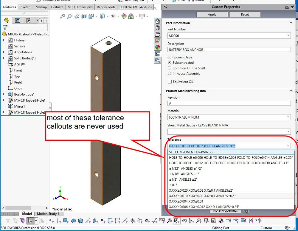
FIGURE 2. When testing the data entry selection list for Tolerance on a part file—that is to say, using FMA.prtprp form—it is noted that the list is very long and very cluttered. The form for parts needs to be corrected.
In the previous episode, we corrected a problem with the data entry form’s presentation of Equivalent OK, something that appears on our BOM tables. That discussion introduced the use of the software tool Property Tab Builder and revealed custom properties as the secret sauce that lets our data stored in the 3D model appear on our 2D drawings.
In this episode we have feedback from staff using our data entry form. The good news is that the data entry field for Tolerance is properly named and works with the drawing template. The problem is with useless selections (see Figure 2).
The list of ready-to-use tolerance callouts is too cluttered with legacy stuff—such as HOLE-TO-HOLE and XXX±. For this project we only want the X.XXX± style tolerance specifications to be in the selection list.
Use Property Tab Builder to open the file FMA.prtprp (see Figure 3). To edit a control on the form, select it. Its attributes will be presented on the right. In this example, Tolerance has been selected, and the list of entries has been edited.
Our edited Tolerance list includes the entry SEE COMPONENT DRAWINGS as a tolerance specification. This selection is sometimes used on our assembly drawings. The other entries range from pretty open to pretty tight (±0.020 in. down to ±0.002 in.). Note the check box in Figure 3 that allows custom (free-hand typing) tolerances just in case this list of defaults is lacking. And we make sure this applies to all configurations.
We test the form using a model of a 3D part and find the Tolerance selection list now is looking great. We need to make this same change to the tolerance defaults for assemblies, as well as for parts. The work we just completed applies only to parts.
We could use Property Tab Builder and edit the form for assemblies. Open the file FMA.asmprp and repeat what we did in FMA.prtprp. But we’re going to hack around in secret places to save some typing. Let’s copy and paste our shiny new Tolerance control from one form to another.
This is risky—in the same league with editing the registry on your computer. Only the reckless would try this trick without having a little understanding of XML.
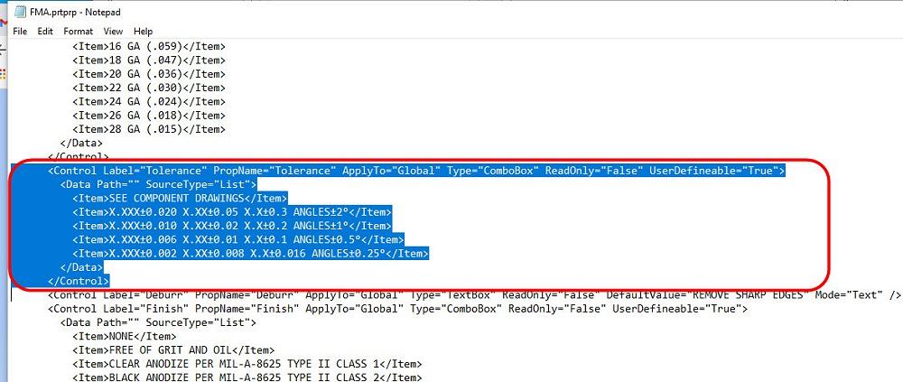
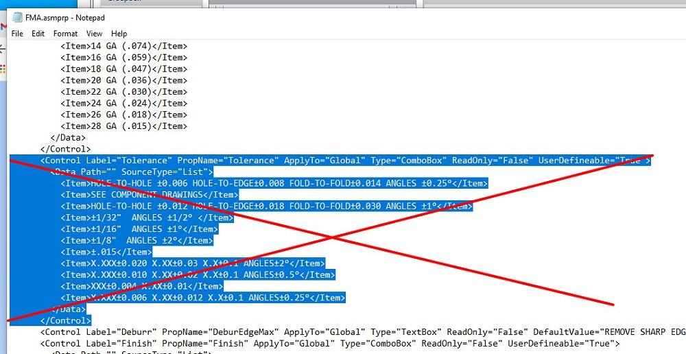
In Figure 4A we see Notepad has opened FMA.prtprp, the file we successfully edited with Property Tab Builder. We located and selected a block of text that is the start and end of the control we want.
In Figure 4B we see another session of Notepad is running, and it has FMA.asmprp open. Somehow the out-of-date Tolerance control was selected, and Notepad deleted the obsolete. If anything went wrong, it is Notepad’s fault, you see.
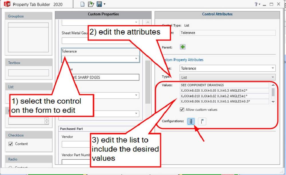
FIGURE 3. To edit the list, open the form (FMA.prtprp), select the Tolerance control, edit the attributes of its list, and save the form. Then test it to make sure the form works well. How do we make the same change to the form for assemblies?
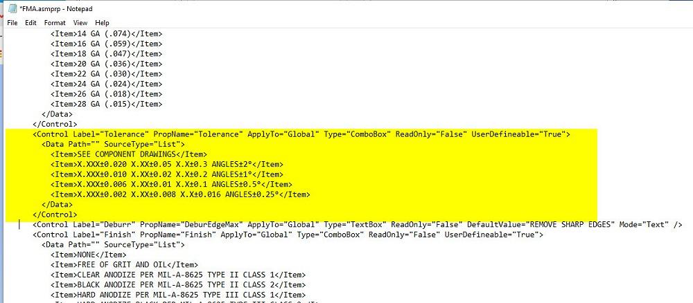
In Figure 4C we heave a sigh of relief with pasted success. The updated control, from its beginning to end, now appears in the right location in the document. One could have pasted onto the selected text to replace it, but we used a distinct delete operation for drama.
What could go wrong with that? Plenty. XML, as a language, is not forgiving. But it is not terribly mysterious. Controls start and end.
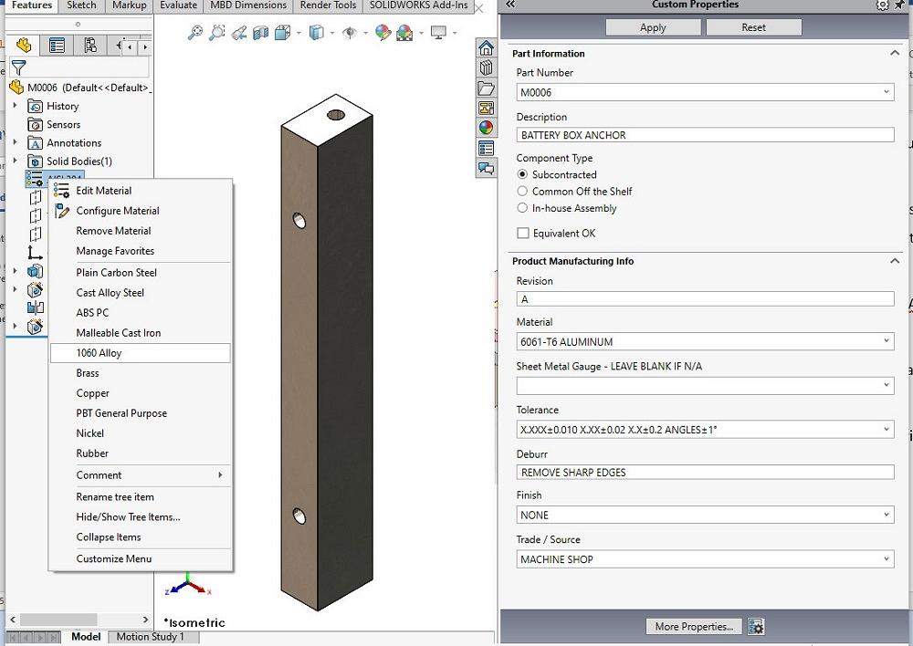
As foreshadowing of future administrative and design work, before we can get back to PMI data entry so we can start making drawings, we need to do some work. Figure 5 shows that our workstation isn’t set up with the correct defaults for materials in the Feature Manager.
The Feature Manager’s material selection applies to mass simulation and analysis. The data entry form, to the right in Figure 5, has a control for Material that has use on drawings. It’s also the PMI. How do we get those separate material settings to match?


The Fabricator is North America's leading magazine for the metal forming and fabricating industry. The magazine delivers the news, technical articles, and case histories that enable fabricators to do their jobs more efficiently. The Fabricator has served the industry since 1970.
start your free subscription
Easily access valuable industry resources now with full access to the digital edition of The Fabricator.

Easily access valuable industry resources now with full access to the digital edition of The Welder.

Easily access valuable industry resources now with full access to the digital edition of The Tube and Pipe Journal.

Easily access valuable industry resources now with full access to the digital edition of The Fabricator en Español.
In this episode of The Fabricator Podcast, Caleb Chamberlain, co-founder and CEO of OSH Cut, discusses his company’s...


